Checking Accuracy
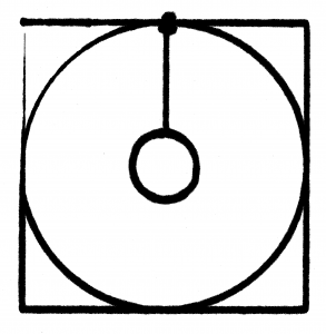
Using my simple router code I had the X/Y table plot a square with a circle inside of it (and then added some extra code to draw a smaller circle inside that). The first time I tried this I found that one side of my X/Y table was significantly (1mm or more) lower than the other. I added a washer between the table and the piece of wood that attached it to the Y-axis drawer pull and that improved things quite a bit ( the washer is on the bottom left corner of the test pattern). Using a felt tip marker gives a good indication of the level of the work platform, as the tip will be pushed up (and spread out, leaving a wider mark) if the table gains height, or get smaller if the table drops. One of my corners (top left in the image) has a distinct dip in it, but because I started the plotter at that corner and adjusted the height as it was moving I need to repeat the test. The giant ink spot in the top middle is because I left the pen sitting on the paper while writing the code to draw the inner circle.
My test pattern (and working area) is approximately five and one quarter inches on a side. By measuring the distance from opposite corners you can also check to see how perpendicular your X and Y axis are. Using my “wide” felt tip marker, the corner distances are both 8 and one-eighth inches. I may find a small difference if I use a more precise marker, but for now I’m happy with the “squareness” of my X/Y axis system. The pattern you see here took over ten minutes to draw, so the IPS of my system is relatively low. The video below shows my plotter drawing the test pattern (The video is sped up to 3 times actual speed.)
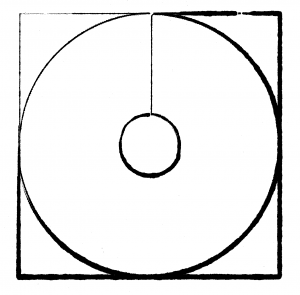
I changed the test pattern code to start at the top middle so I could adjust the pen somewhere other than the top left corner and found that the top left corner was also low.
So, I added a washer to that corner as well. I then re-did the test pattern. This time I did not draw the circles. I plan on using OpenCV to do some line detection on this four line box to see if I can get a highly accurate measure of the distance of the diagonals. It appears that my washer (shims) are slightly wider than I need and the “washer” side is now slightly higher than the non-washer side. However, it is better than it was before. Once I get my Z-Axis working, I may re-visit this issue to prop up the other side with some very narrow shims (heavy paper?), but I expect this is level enough for cutting out parts to make a 2nd gen router.
