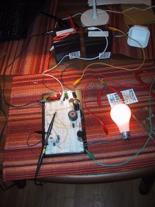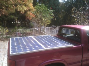
A boost converter is a dynamic electronic circuit that can “boost” a lower voltage up to a higher voltage. Current is of course reduced in the process, but if you design it right you only lose 5-25% of the overall power. I am in the process of building one that will convert the approximately 70 volt nominal output provided by my solar panels into 125-140 volts that will charge my trucks batteries. I also plan on adding a bit of maximum power point tracking and battery charge regulation to the control logic, making it a MPPT solar boost converting charge controller. Why do I have all of these wires and parts scattered across the dining room table? Because the market does not sell what I need. (Believe me, I’ve looked.) So I have decided to build what I need.
Not being an electrical engineer, I probably won’t be able to get 95% efficiency out of my system, but so far I’ve measured 85-90% efficiency when doubling voltage. [Test 1: 23 volts in at 0.28A for 6.44 watts, 46 volts out at 0.12A for 5.52 watts means 0.92 watts loss = 0.92/6.44 = 0.142 or 14.2% losses. Test 2: 34.8 volts in at 0.35A for 12.18 watts, 72.3 volts out at 0.15A for 10.84 watts, or -1.335 watts loss, which is 10.9% losses.]
I’m still running things off of a (relatively) low voltage and current supply (two/three 12V 5AH batteries) while getting everything working, and only boosting up to 50-72 volts when testing.
I had the circuit up to 95 volts (max of 16 watts) on the output side, but I really want to optimize it for a voltage doubling, and you lose a good amount of efficiency when going higher than a 50% duty cycle.
I have also not been able to find a commercially available boost regulating control IC that works with 100 volt inputs and produces up to 200 volt outputs. One probably exists, but digikey doesn’t appear to have it. I’m solving this problem by programming my own using a PIC micro-controller. At least the programmable nature of my controller should also allow me to add the battery charging maximum voltage/current and solar panel MPPT logic into the system. I am currently working on a single phase boost converter, but the plan is for the final system to be two phase (which basically means that I use two of them in parallel). This means that I need my single phase system to be able to support 100-175 watts maximum. Soon I’ll be moving from my 25 watt resistive load (25 watt lightbulb) to a 100 watt resistive load. Eventually, I may even borrow a 75 volt power supply and test it up to 140 volts.
While working on my boost controller, I’ve found the following reference links very useful:
- http://www.ladyada.net/library/diyboostcalc.html
- http://www.nerdkits.com/videos/backlight/
- http://www.daycounter.com/Calculators/Switching-Converter-Calculator.phtml
- http://www.arrickrobotics.com/highload.html
I have also made a few mistakes that people making their own boost converter may want to avoid:
- Within reason, the higher the switching frequency the better. I started off using a PIC12F683 chip which only has a single PWM output. Because I was planning on building a two phase system, I decided to code my own PWM loop that would support two phases with a 180 degrees difference. (A fancy way of saying that they would each be ON for the same amount of time, but that while channel A’s ON time would start at the beginning of the period, channel B’s on time would END at the end of the period. If the duty cycle went above 50% they would overlap for a bit in the middle.) After spending an hour on my fancy 2 phase PWM system and testing it with some visible LED’s, I took all of the delays out of it only to find that my 8Mhz internal oscillator could only support a period of 1.5-3 kHz. Sure, it sort of worked, but you could HEAR it switch. It also required a much larger inductor for the same power. So, I switched over to using the built in PWM subsystem, which can easily hit 73 kHz while still having 5-6 bits of precision. I now plan on switching over to a PIC 16F chip which has a dual channel PWM that I THINK can do an 180 degree 2 phase signal in hardware (if I’m reading the specs correctly…)
- Most MOSFETs require at least a 10 volt gate signal. If you switch them with a 5volt logic signal directly from the PIC they will switch (at least mine did), but they will not carry current without burning a lot of it up as heat. I was wasting 80% of my power as heat in the MOSFET until I wired up a transistor off of a 12V rail to amplify the signal to 12 volts. I plan on using a IXDN604PI gate driver chip for my final design.


Pingback: Boost Converter Schematic — Jay’s Technical Talk