To test the resonant frequency of a Tesla coil or other resonant circuit you need an oscilloscope (which I have) and a signal generator (which I didn’t have). I was able to follow these instructions from RM Cybernetics to build one from a 555 timer and use it to test my primary and secondary.
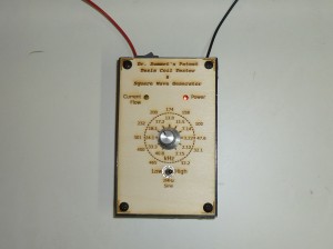
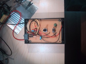
The only modifications I made to the circuit was the addition of a toggle switch so that I could use two different capacitors, giving a “low” and “high” frequency range (plus a “air gap” capacitance that basically runs the 555 as a 2Mhz sine wave generator). I built the circuit on a protoboard that came with a box, and decided to use a laster cutter to make the instrument panel. To do this, I opened up Inkscape to design a control panel using vector graphics. I would print each design out and tweak it until it fit my box and circuit perfectly. I then tested various dial positions on my 10K audio scale (logarithmic) pot using my oscilloscope to mark the approximate frequency on the dial. After a few trials, I was able to laser cut the design onto a piece of 1/8″ craft plywood to get the finished product.


