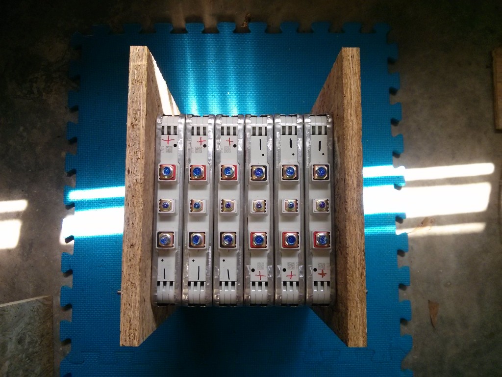
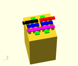
This is a mockup of the eight batteries that I’ll be building out of my 48 leaf modules. The final battery will probably be using marine grade plywood, or possibly even steel compression plates.
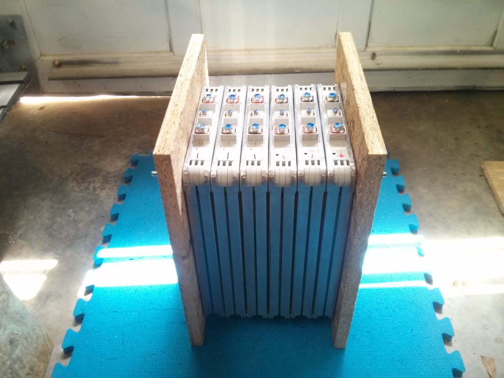
I am arranging the modules into a 3 parallel, 2 series layout, giving around 16 volts and 180 AH per battery. (128 volts and 180 AH for the entire system).
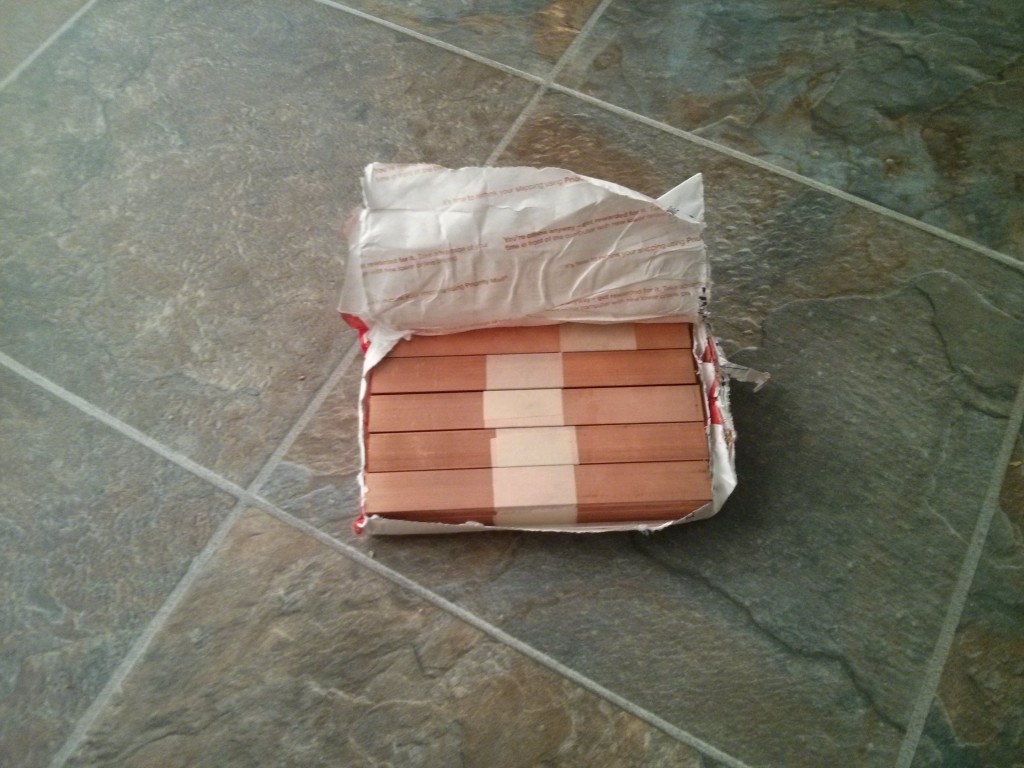
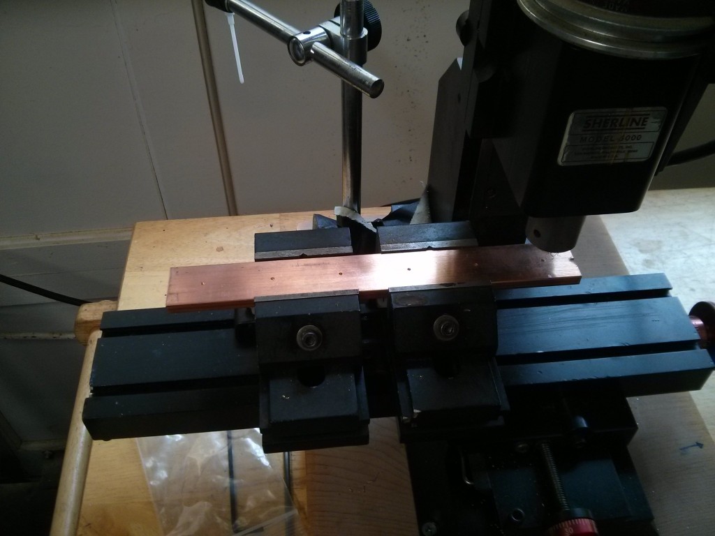
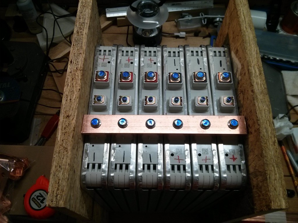
Of course, to put them in parallel, I need some busbars…cue the 16 lbs of copper.
You don’t NEED a milling machine to place six holes exactly 1.3333 inches apart….but it helps.
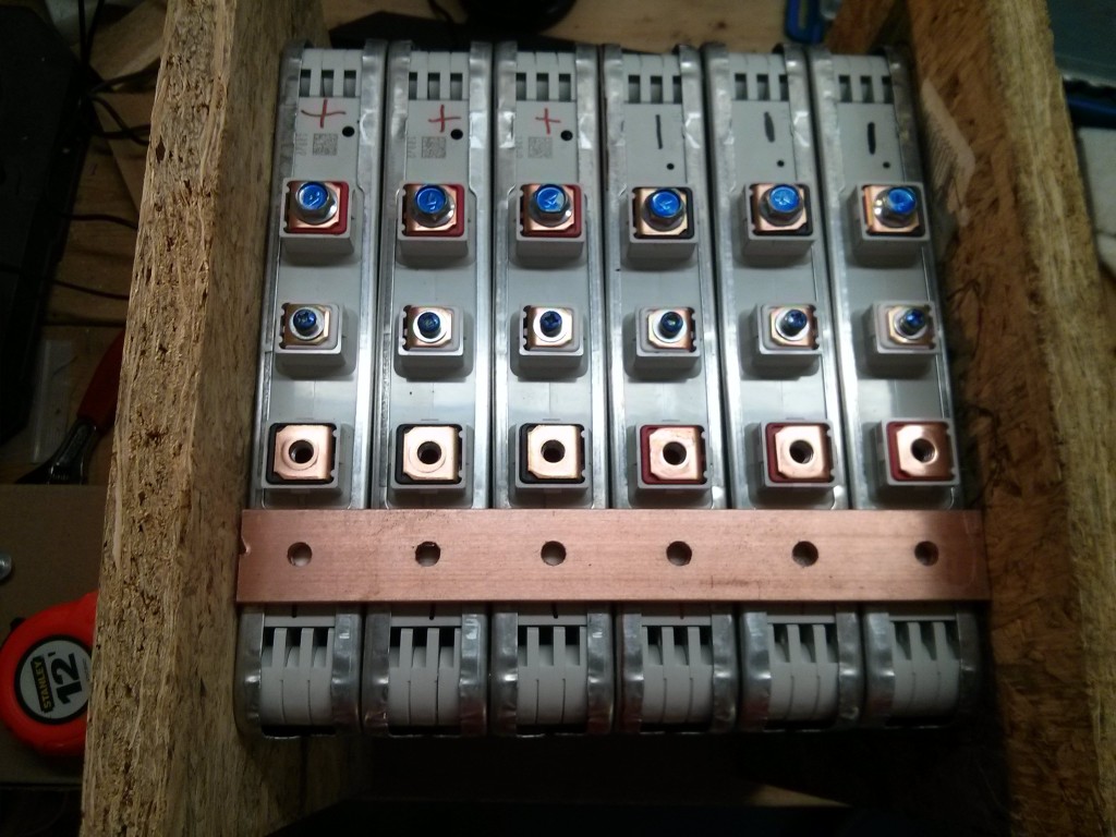
I COULD have done that by hand….but it’s a lot easier (and more repeatable) with the mill. If I was doing it by hand I would have used a larger drill bit to make the holes slightly wider, it’s not like I’m tapping them or anything….
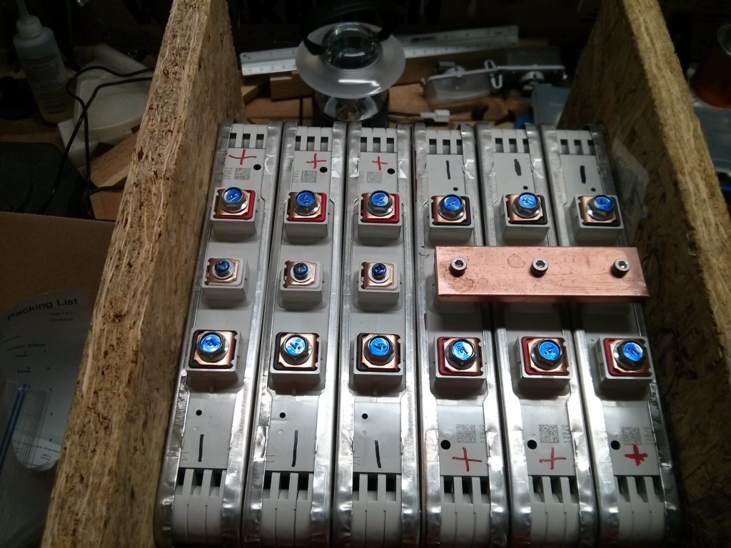
The Leaf modules actually have 4 cells inside of them, in a 2P2S arrangement. This means that the center “sense” post is actually between two cells, and halfway between the positive and negative side of the battery in voltage. I connect the cell level miniBMS boards to the sense lines. I have also decided to tie the sense posts together to make sure that the cells inside the three parallel modules stay in balance. (I wouldn’t want a miniBMS board to be drawing 4mA from only one of the three cells.) I used the same 1/4″ by 1″ bussbar on the sense posts as I’m using for the rest of the battery. This is completely unnecessary, as they shouldn’t be carrying any current to speak of, and I could have saved some money by buying a second (thinner) set of busbars specifically for the sense posts, but I decided it was easier to just use the same busbar size everywhere.
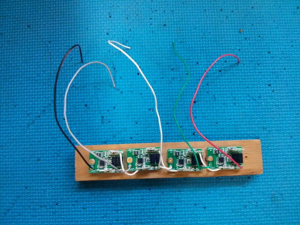
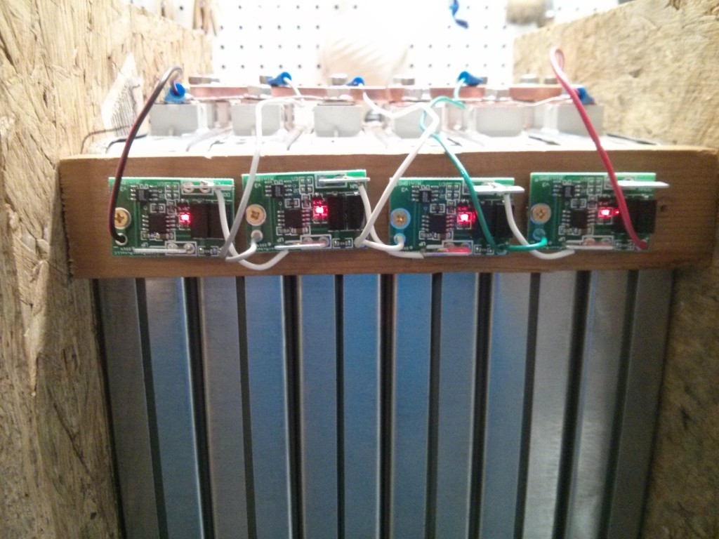
I bought individual miniBMS modules. They sell a board that is basically 4 modules connected together, and it looks like I should have bought those instead. (I wasn’t entirely sure that I was going to be going with a set of 4 cells (2 sets of 3 modules) per battery, so I wanted the flexibility of individual boards. With 30 minutes of soldering I can turn four of them into an equivalent circuit…
Because it looks like I’ll have to mount my batteries “sideways”, I put the miniBMS boards on the side (so they will be UP and visible when mounted in the truck). After test fitting the battery in the truck I will probably move the 4 miniBMS boards to be “vertical” instead of “horizontal” as this picture shows, so that the 00 welding wire for the main power terminal won’t have to run over them.
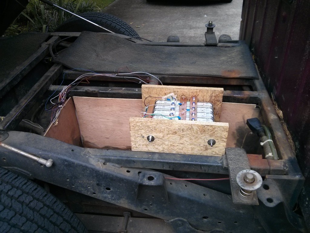
This is the battery module “in the truck” in one of the two side battery bays. I’ll be placing two of them in the bay sideways.

Sweet Project,
Can you share some specific dimensions from the leaf cell? Ideally the true height to the terminal blocks. There is very few information online to design with.That or sharing your CAD model and I would be super grateful. Thanks
I have posted the cad file and my measurements here:
https://www.summet.com/blog/2015/08/20/battery-bay-plan-nissan-leaf-cells-six-group/
The terminal blocks are 20x20mm (18x18mm for the center sense terminals) and “about” 25 mm tall. (that includes the height of the bolt head when it’s in them too.)