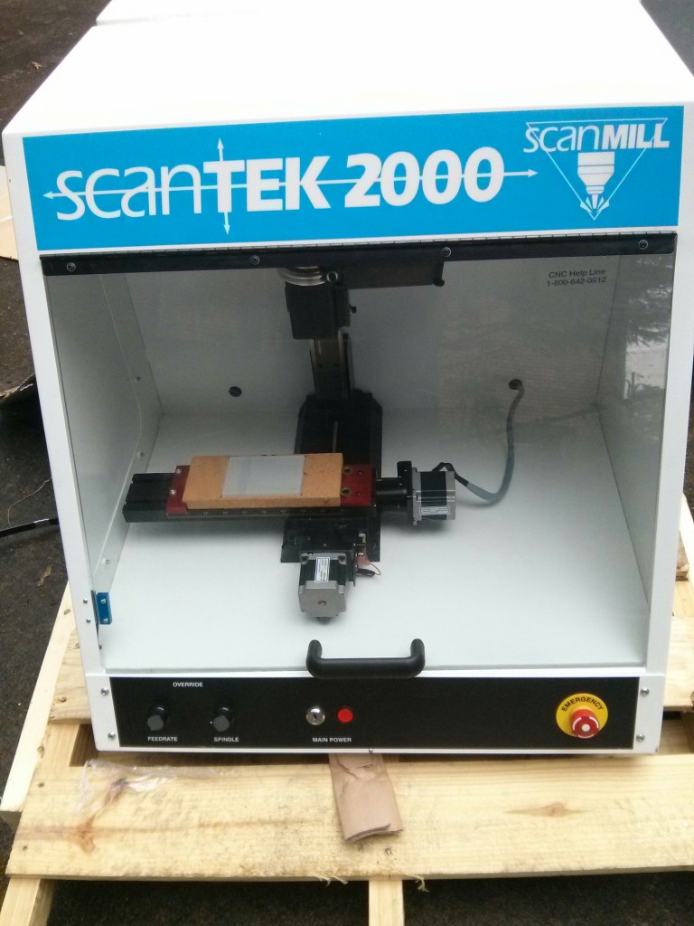
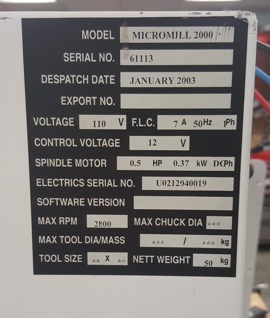
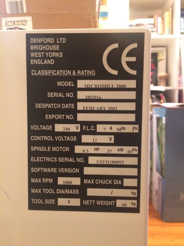
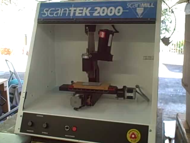
This is a ScanTek 2000, a rebranded Denford Micromill 2000 that has a CNC controlled Sherline mill in a nice steel enclosure with some fancy CNC electronics. According to the nameplate, it was dispatched in October 2005, so a relatively newer model.
They are designed for technical schools and shop classes to teach students the fundamentals of CNC machining without having to have a really large CNC mill. Although the Sherline Mill inside is relatively small, it is still a serious mill and can be very precise and even mill mild steel. I purchased mine surplus, and it unfortunately did not come with the key for the front panel power switch, or the software to drive the mill. My first goal was to see if I could get it to turn on.
This is the front panel. It has some pots you can turn to override the feedrate or spindle speed, a keyswitch and light up indicator for the main power, and a very nice Estop button. (If you hit the Emergency Stop button, you need to rotate it to disengage before anything works again.)
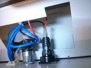
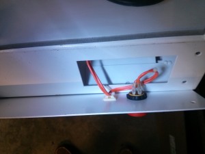
I took the front panel off to investigate the keyswitch, and documented all of the other wires so that I could try and trace them to the back of the machine.
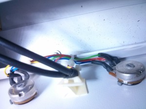
From the left….small wires on the override pots. The feedrate pot had darkblue/lightblue, Yellow, and Red.
The Spindle pot had darkblue/darkblue, Green, and Red/Red.
I believe that the small Yellow wire is the sense input for the Feedrate override, and the small Green wire is the sense input for the Spindle override. I suspect the two blues and two reds are ground and + voltage. The red ones have a single source, while the two blue ones are tied together, but look to lead back to two different places.
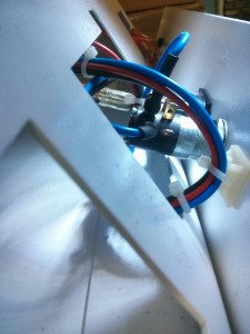
The keyswitch has two large blue wires, and the power indicator light has thick red and black wires.
The EStop button has two large orange wires.
The main power board in the back of the enclosure has a connector that is labeled “Front Panel”. Look at those wires…
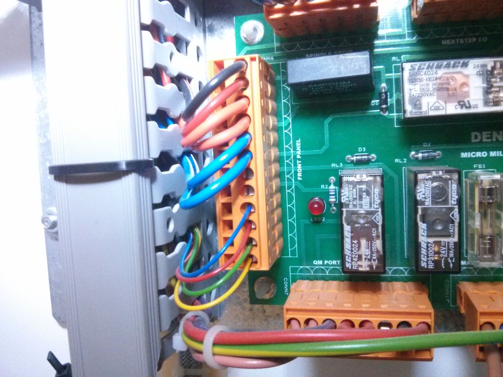
From the top, it looks like the power indicator light, Estop switch, Keyswitch, and possibly also the override spindle wires. (One blue wire may be going somewhere else?)
When I turned on the main power switch on the side of the enclosure, the power indicator light on the front panel lit up. This gave me hope that perhaps the keyswitch was already in the “on” position, and did not need to be hot-wired. So I observed the pattern of blinky lights on the diagnostic LED’s and 7 segment display on the main control board.
- Applied power. Power indicator light at switch came on.
- Power indicator light on front panel came on.
(possibly indicating that keyswitch is locked in the
“on” position?) - On the back, the red 24 V led on the power board illuminated. (LED 2 on the other side of the power board near the “Front Panel” connections did NOT illuminate.)
- The exhaust fan turned on, and the florescent light inside the case came on.
- On the main motion control board, led’s lit up and flashed.
- Red LED lit briefly and went out.
- Green LED lit up.
- Orange LED lit up, green LED then went out.
- (7 segment display, center crossbar lit, period started to flash)
- Orange LED remained lit, green LED started to flash.
- On the 7 segment display, the crossbar and flashing period were replaced by an E. The E was replaced by an S (or 5?) The 5/S was replaced by an L with the center bar lit. That was replaced by a lowercase O (bottom of 7 segment display) That was replaced by a P.
After this, the pattern (E 5 L o P) was repeated continuously.
So, it’s not completely dead.
I found the following list of error codes in an online manual:
So it appears that there may be an E – “Software abort or interpreter error.” S – “Stop asserted”, L- “Limit switch open” (the L had a bar on it, so I will assume that is combined with the – “Servo Power Off” message. As well as o-“Offset Mode” and P – “Linear Position Mode”.
This could indicate that I need to work with the keyswitch a bit more, or perhaps try and move the axis away from any limit switches and try again to see if anything changes.



I just want to thank you first of all for all your info, its been super helpful in getting to the point Im at with the same mill. Im using cnc linux and theres alot to fine tune. Just wandering how you configured your steppers. Right now im just using the preset shurline configuration and its working… But Im having a hard time finding the exact stepper motor driver info … Thanks again!
I’m also using the preset Shurline config, and haven’t found any problems with it.
About to embark on this Mach3 conversion on an older Denford unit. Has the pre-Baldor Optimised Control board installed (which is the same 96 pinout as I understand). Thanks for putting the time in putting all the documentation and videos together so hoping this goes smoothly!!
Good luck! I believe the 96 way pinout should still be the same for you.
Thank you sir. Quick question…It has the old, round style stepper motors. Are these easily replaced or do I need to swap out more electronics? I read that they are limited in their torque rating.
Thanks, Jay
I’m afraid I don’t know for sure. As long as they are steppers (and not DC servos or something else) I would expect that any modern stepper driver electronics would still be able to drive them. I would be more worried about the hardware/mounting systems. If they use the standard NEMA bolt hold patterns and shafts it should be just a simple matter of buying new steppers and bolting them on. But if they have different shafts or bolt patterns, it could require a lot of adapters to make them work and may not be worth the effort. Presumably they were “good enough” for the mill when initially installed, so you might want to see if you can get them working with a regular stepper driver and only swap them out if they don’t meet your needs.
Do you know what model the sherline mill is . I’m at a cross road .. I have the opportunity to look at both for the same price .. sherline 5400 and a scantak2000 are my opinion
The Z axis travel is 160mm (6.25 inches) and the travel in the Y is 130mm (5.11″) so I believe the Sherline mill inside the case is the 12″ model (5400 series) as opposed to the 10″ model (5000). The big difference I see between the Sherline CNC offering and the Scantek is that the Scantek includes a case (but requires proprietary software or a lot of work to interface with a breakout board to work with generic software) while the Sherline 5400 CNC model is set up to work with LinuxCNC or Mach3/4 out of the box but does not have a case.
If you get the software/dongle with the Scantek2000 it’s a great deal, otherwise you need to spend some time and a little money to make it compatible with LinuxCNC. Having the enclosure is nice for safety (in educational settings especially) but not really required if you are the only one using it. If I had a choice between a Sherline 5400 CNC and a ScanTek2000 for the same price I’d probably go with the Sherline 5400 CNC. But Mill wise, they use the same mill. (The stepper motors/drivers in the ScanTek2000 may be a bit stronger, but you probably won’t make use of that…)