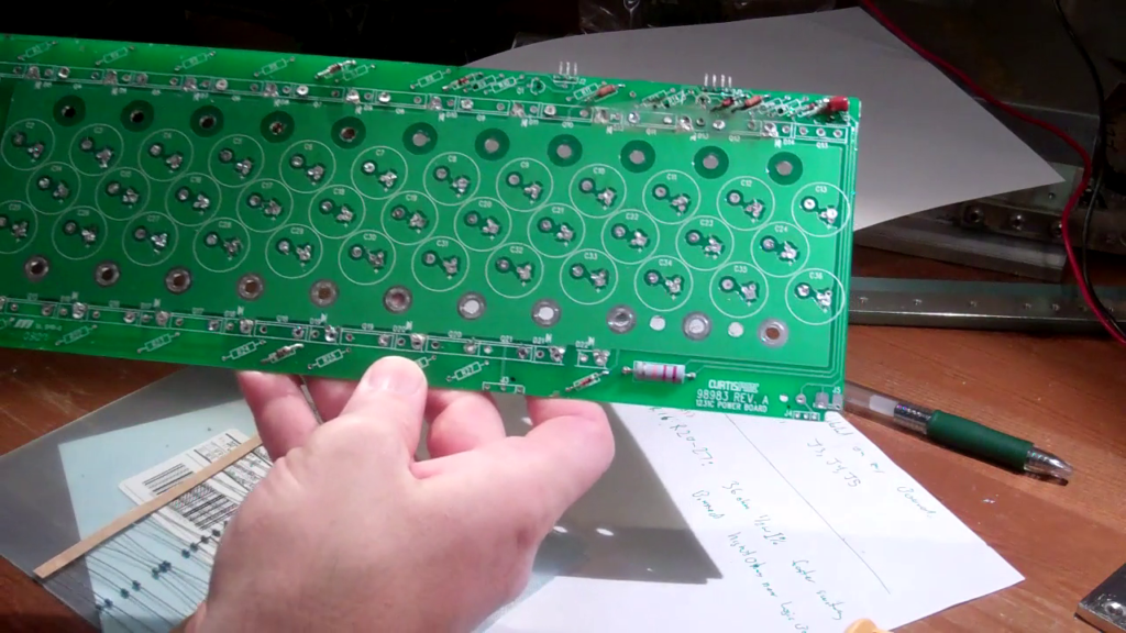
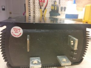
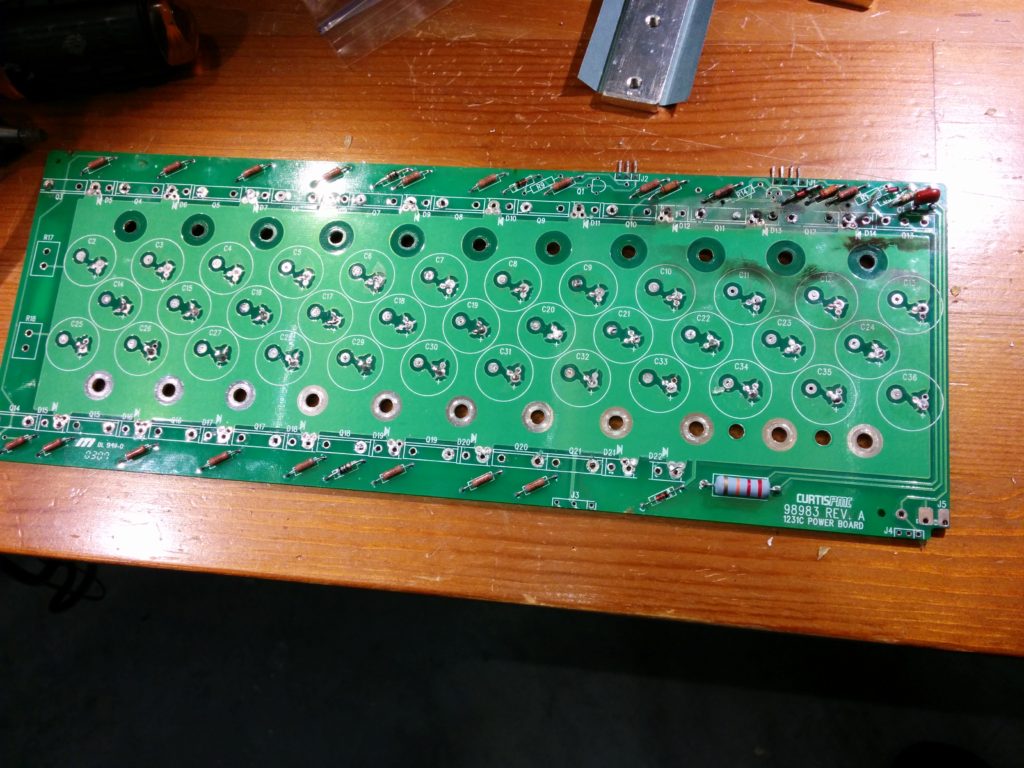
I am upgrading the power board of my Curtis 1231c DC PWM motor controller. It uses 18 MOSFETs to switch the power, and each MOSFET had a 47 ohm resistor on it’s gate input. The point of such a high resistance was to slow down the switching of the MOSFET’s so that they would all share the current somewhat equally and no single MOSFET would turn completely on before all of the others had a chance to start shouldering the load.
The Curtis 1231C typically fails with a few MOSFET’s closest to the logic board vaporizing, probably due to switching on before the others, as the distance to the logic board is the smallest. This is due to the poor PCB layout which has some MOSFET’s much closer to the logic board than those on the other side of the board. The 47 ohm resistors counteract this somewhat, but the slow switching leads to extra heat and less efficient operation, as the resistance of the MOSFET while switching is higher than when it is fully on.
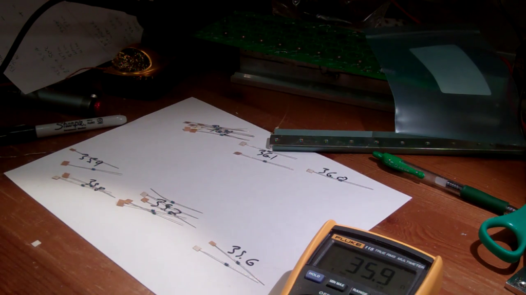
The replacement MOSFET’s have a higher maximum amp capacity than the components they are replacing, so I am hoping they will tolerate a slightly faster switching time. When replacing the 47 ohm resistors, I purchased 35.7 ohm, 1/2 watt, 1% tolerance resistors, and then binned them. I placed the resistors with the higher resistance closer to the logic board, in the hope that they will counteract the propagation delay due to the circuitous routing on the PCB.


