BEME ERod motor drive unit failures

I have purchased three BEME Erod motorized drape systems (one in a previous house, and two in the current house). They have an infrared (IR) remote control that allows you to open and close the blinds at a push of the button, which is very useful if you have things in front of the blinds that make it hard to access the window, or if you just want to be able to open or close your blinds without getting out of bed.

Two of these units have worked flawlessly for several years. My third unit however has had two separate failures which I suspect may be due to poor quality parts.

The first issue crept up slowly, starting out as an intermittent delay in closing. The blind motor would make a “click” when you pressed the close button, but the motor would not engage for 20-60 seconds. Over time, the delay got longer and longer until eventually the blind refused to close. (Although the relay inside would still click when the button on the remote was pressed.)

Diagnosing this as a relay contact failure just from the sounds it made, I opened up the unit, found the part number on the relays, ordered replacements and (for good measure) replaced both relays. (I bought 5 of the relays, so I’m all stocked up for future relay failures.)
two blue relays on a circuit board.

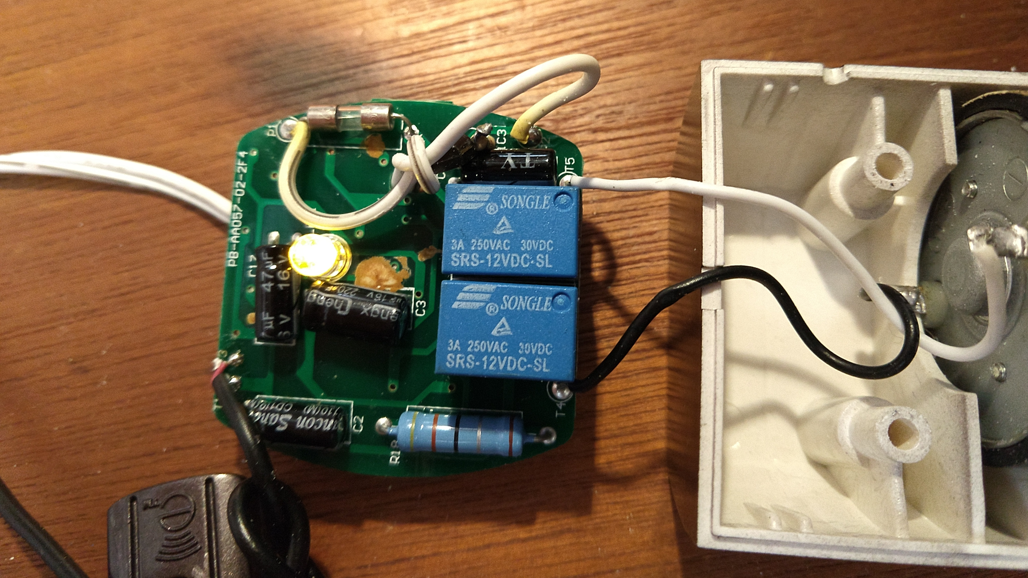
When I had the unit open, I noticed that there was one extra red “re-work” wire on the circuit board, indicating that the PCB had a problem (either a trace left out of the design, or not correctly connected on the PCB during manufacture.) and had to be repaired at the time of manufacture. This is actually more common than you might expect on inexpensive consumer goods, and since the motor was working well with the new relays, I closed things back up.

Around six months later, one night with no prior warning, the motor failed to respond to the remote control completely. No clicking, so the problem probably wasn’t the relays.

Here was my diagnosis procedure:

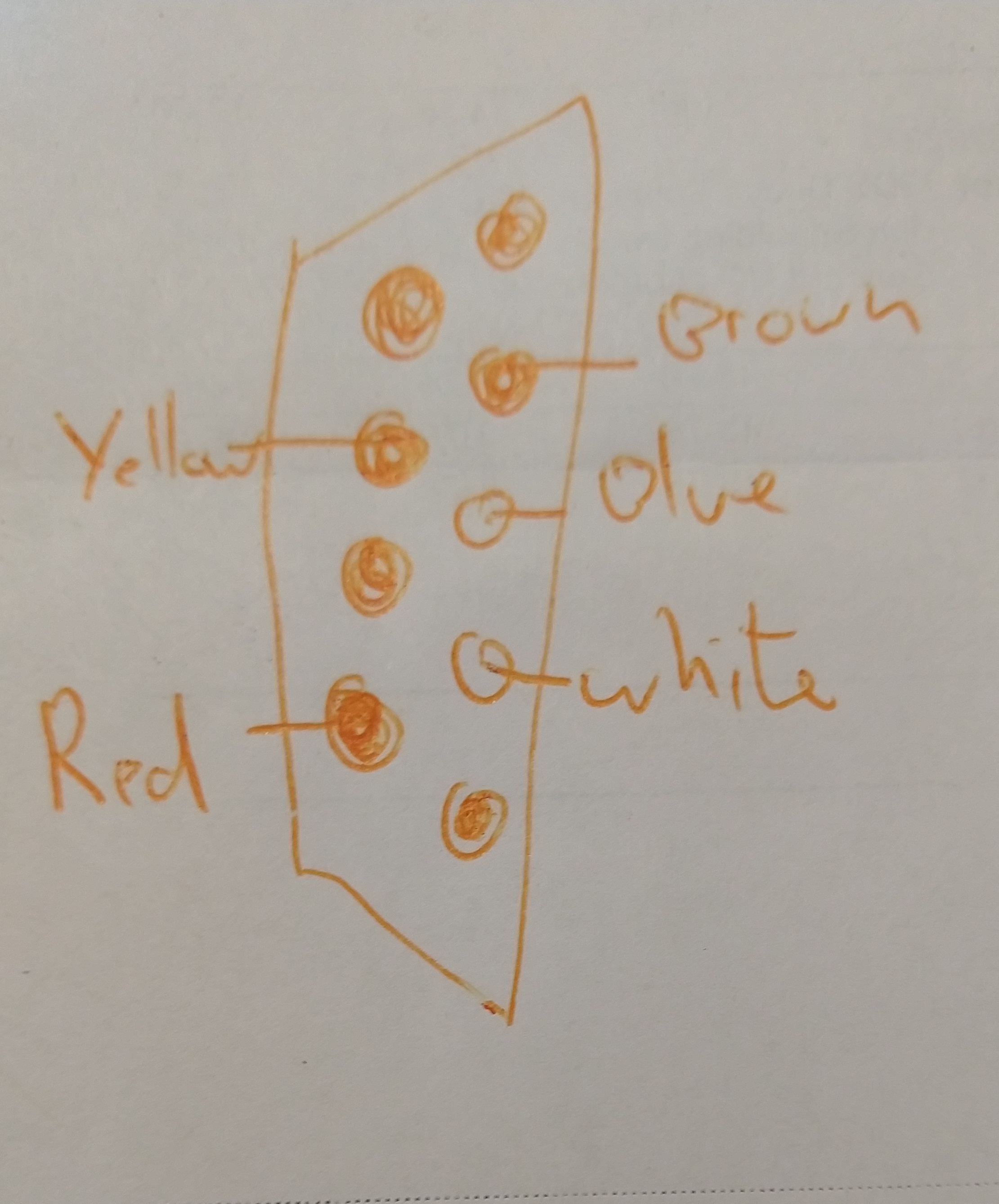
  • I tried the remote on my other erod (despite the fact that the red light was lighting up when I pushed the buttons) to make sure the remote was working.
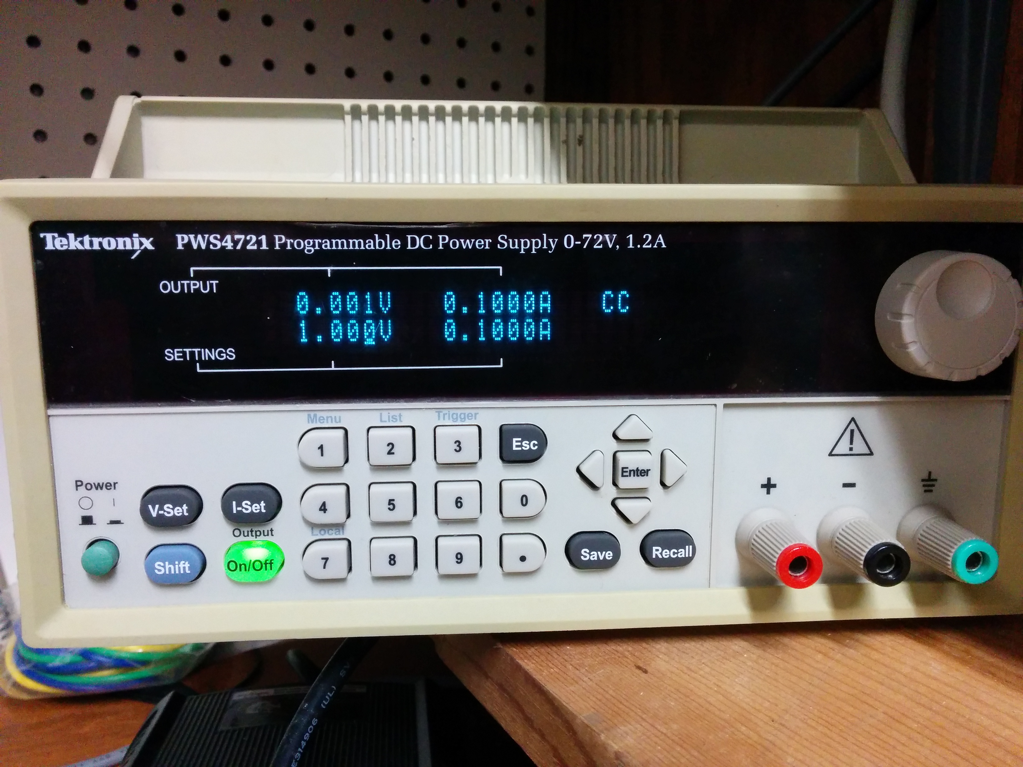
  • Because the motor unit was acting as if it was not receiving any power (completely dead), I took the power adapter and tested to make sure it was providing power by using it on my other (working) erod.
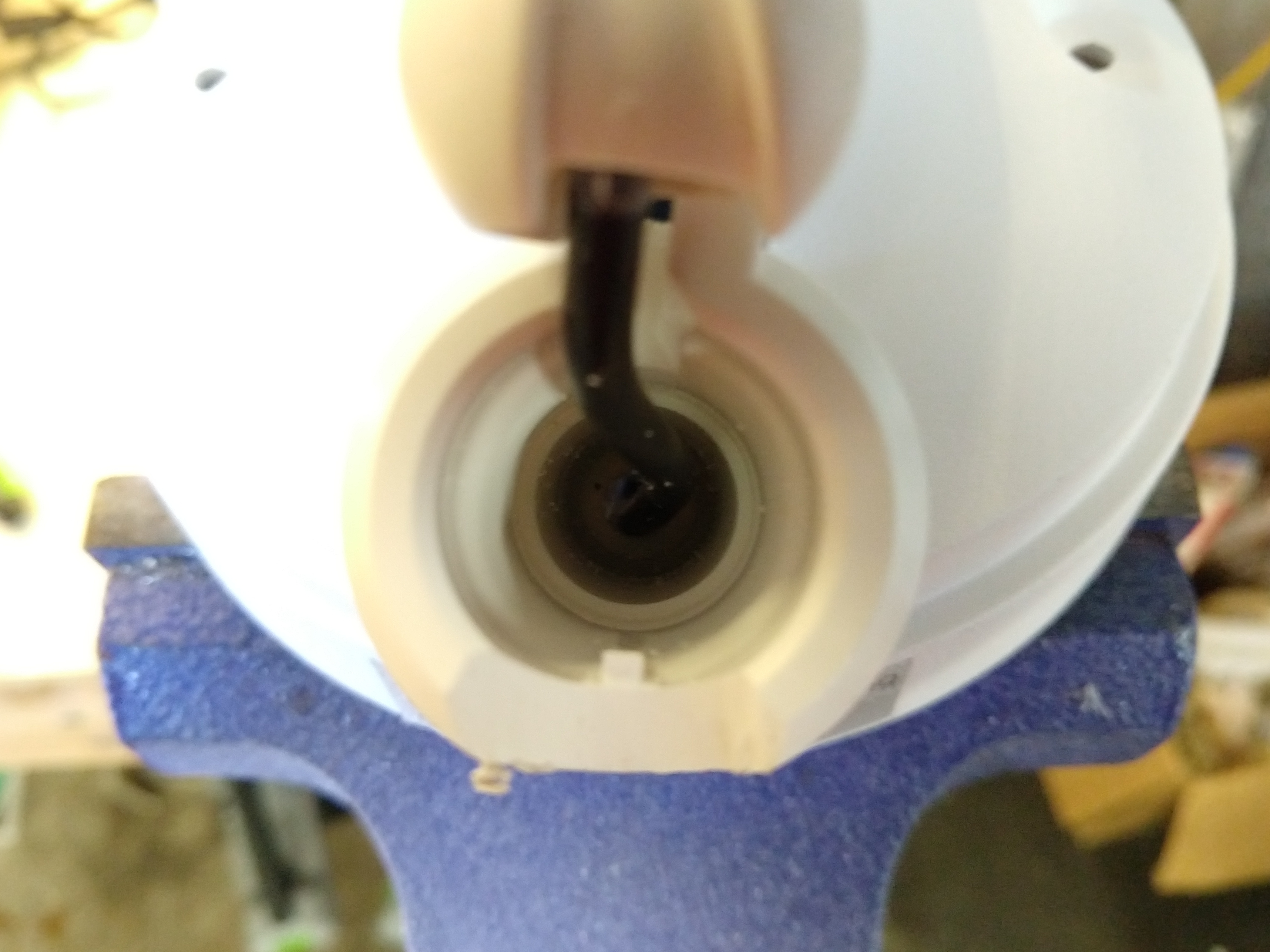
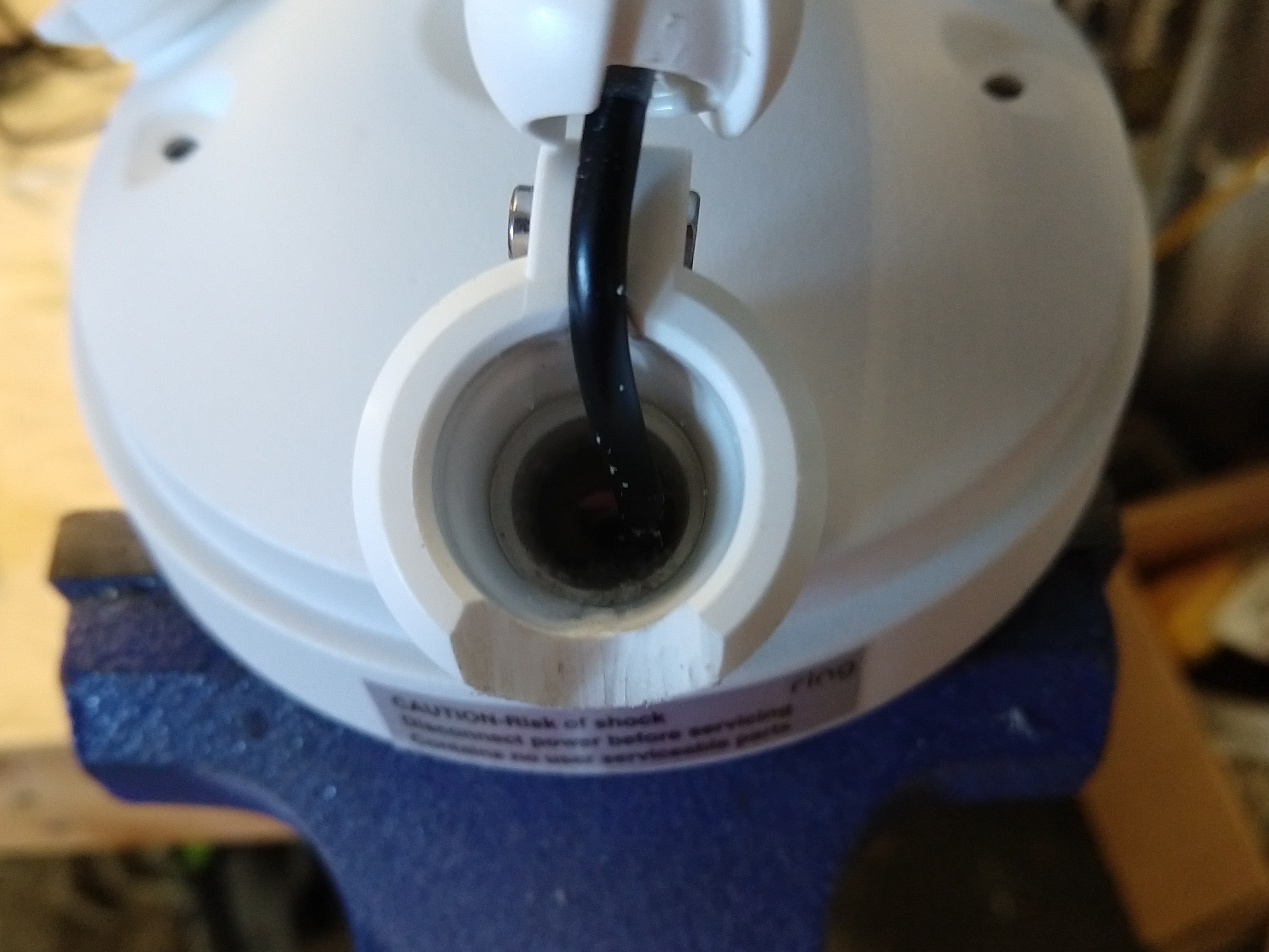
  • Now that I had determined that the problem was definitely with the motor unit, and not with the power supply or remote, I disassembled the motor unit.
  • I checked the fuse on the circuit board, as it is the first possible reason power might not get into the circuit, but it was fine. (Also, a small yellow LED on the circuit board was dimly illuminated when plugged in.)
  • I visually checked the capacitors to make sure that none of them were leaking.
  • Since I had a diode tester mode on my multimeter, I checked all the diodes (but didn’t really expect them to have failed….)
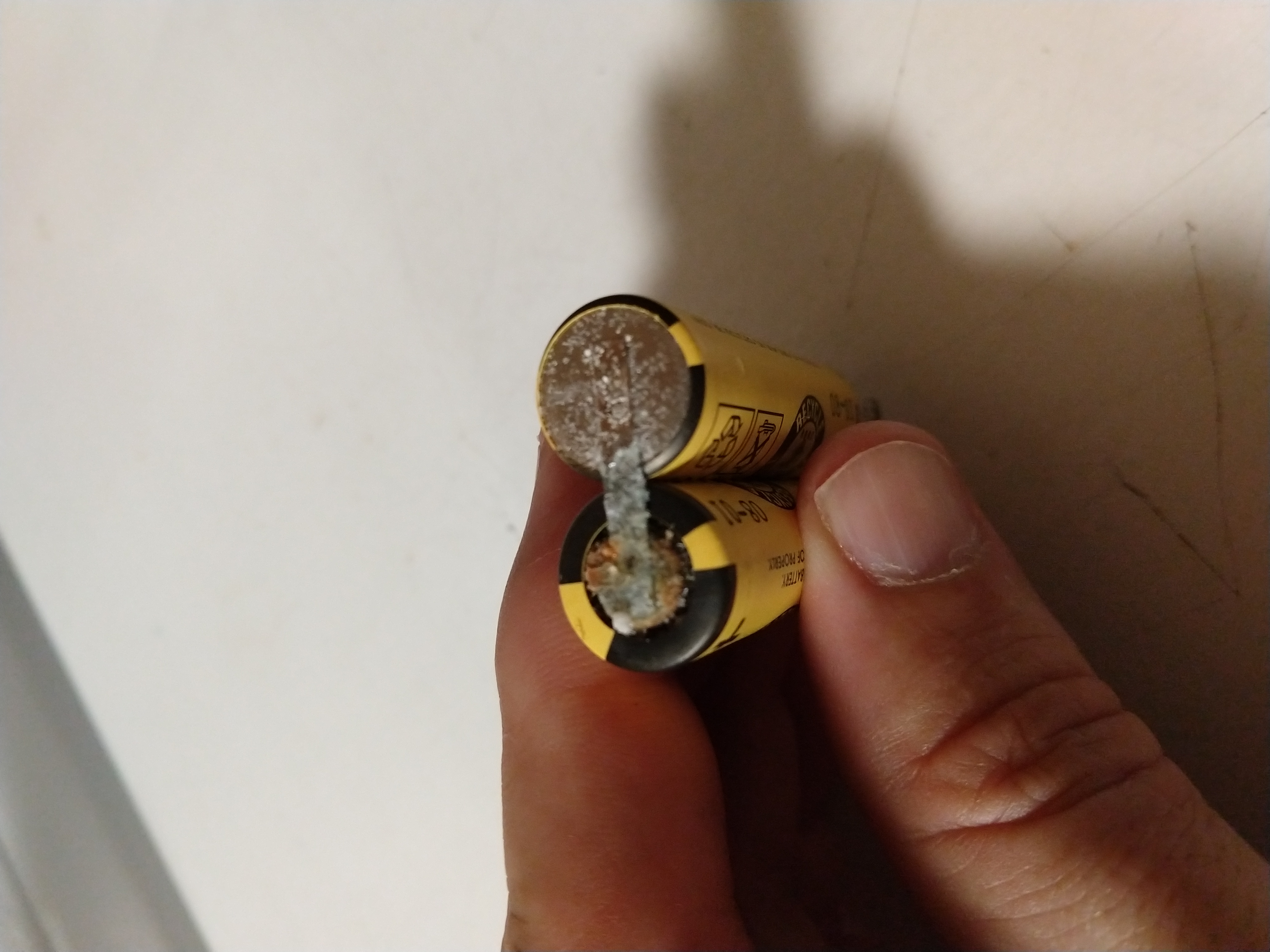
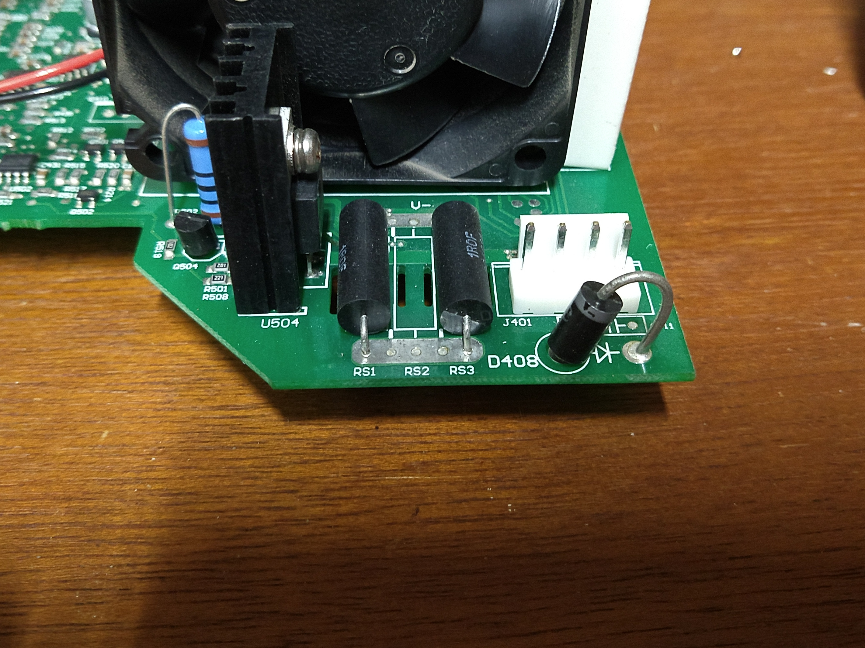
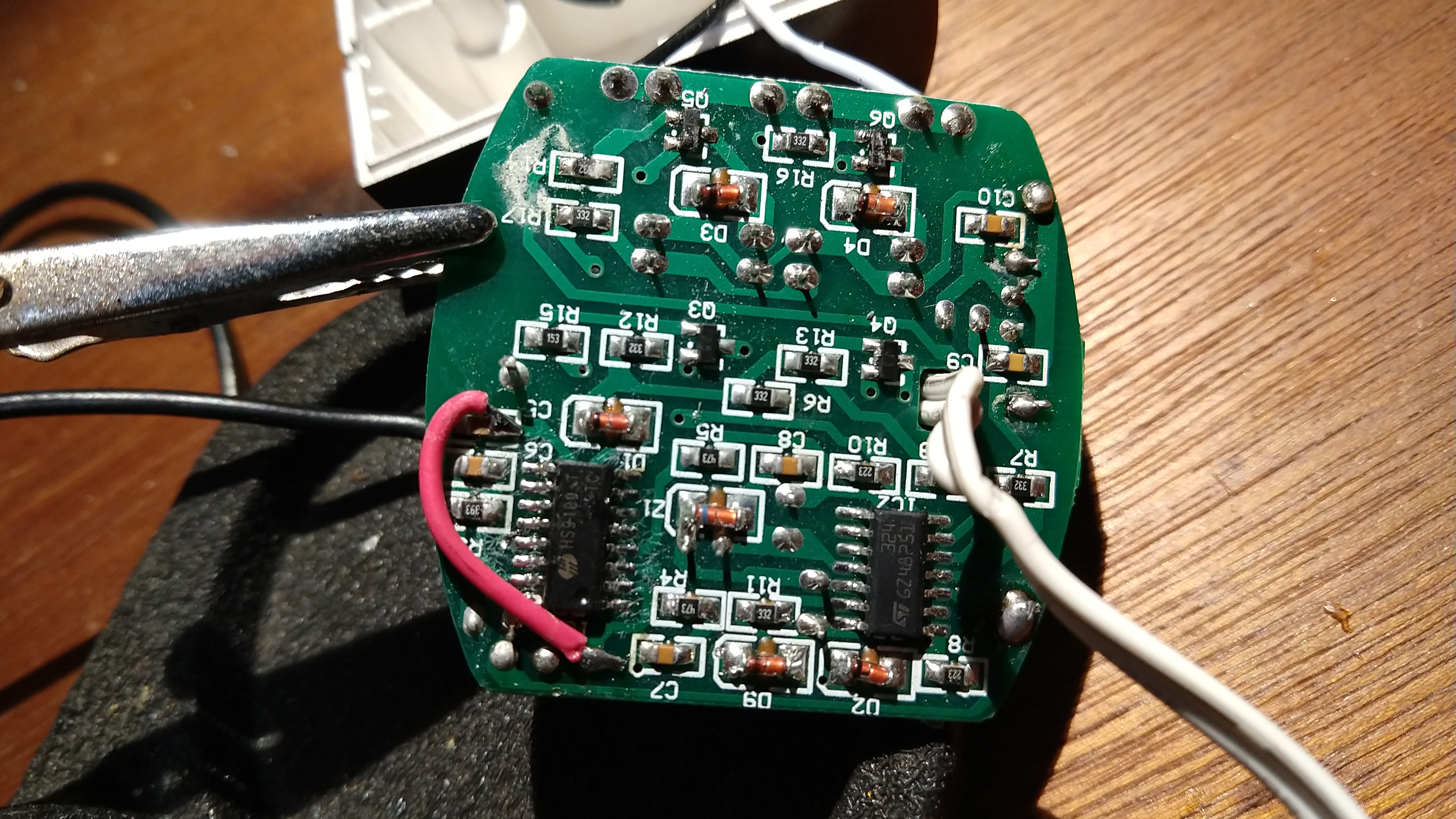
  • At this point, I noticed something funky on the circuit board. A small black component had one of it’s legs replaced by a resistor.   (You’ll probably have to zoom into the photo to see it.) Normally, if a resistor is called for in a circuit, it will have its own location on the circuit board. This resistor was definitely added in later in the manufacturing process, and was not part of the original circuit board design.   Since I hadn’t found anything else that would explain the failure, I felt that investigating this part was a good idea.

78L05 power regulator with a resistor replacing it's input leg

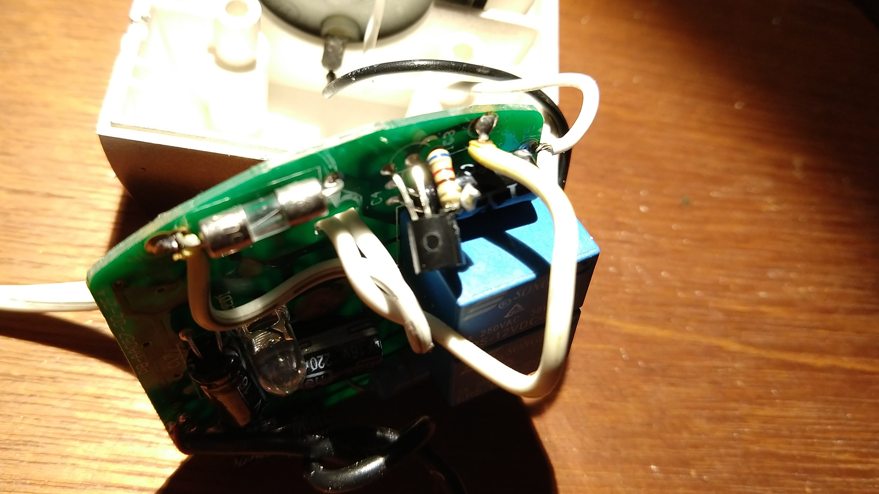
  • The part is a 78L05 linear power regulator, which steps the 12v input down to   5 volts suitable for powering the microchips that watch for the IR remote control signal and trigger the relays (via transistors).   The small yellow led was illuminating on the board when power was applied, so the 5 volt power rail should be working….but, the whole resistor leg looked dodgy to me. When I measured the voltage coming out of the 78L05 regulator, it was only 2.7 volts!   (Just enough to illuminate the LED dimly, but not enough to run the other ICs.) After looking up the spec sheet to make sure that it wasn’t a 3.3 volt regulator, and really was supposed to be outputting 5 volts, I knew that either the power regulator was faulty, or something farther into the circuit was drawing so much power that it was not able to provide the proper voltage.
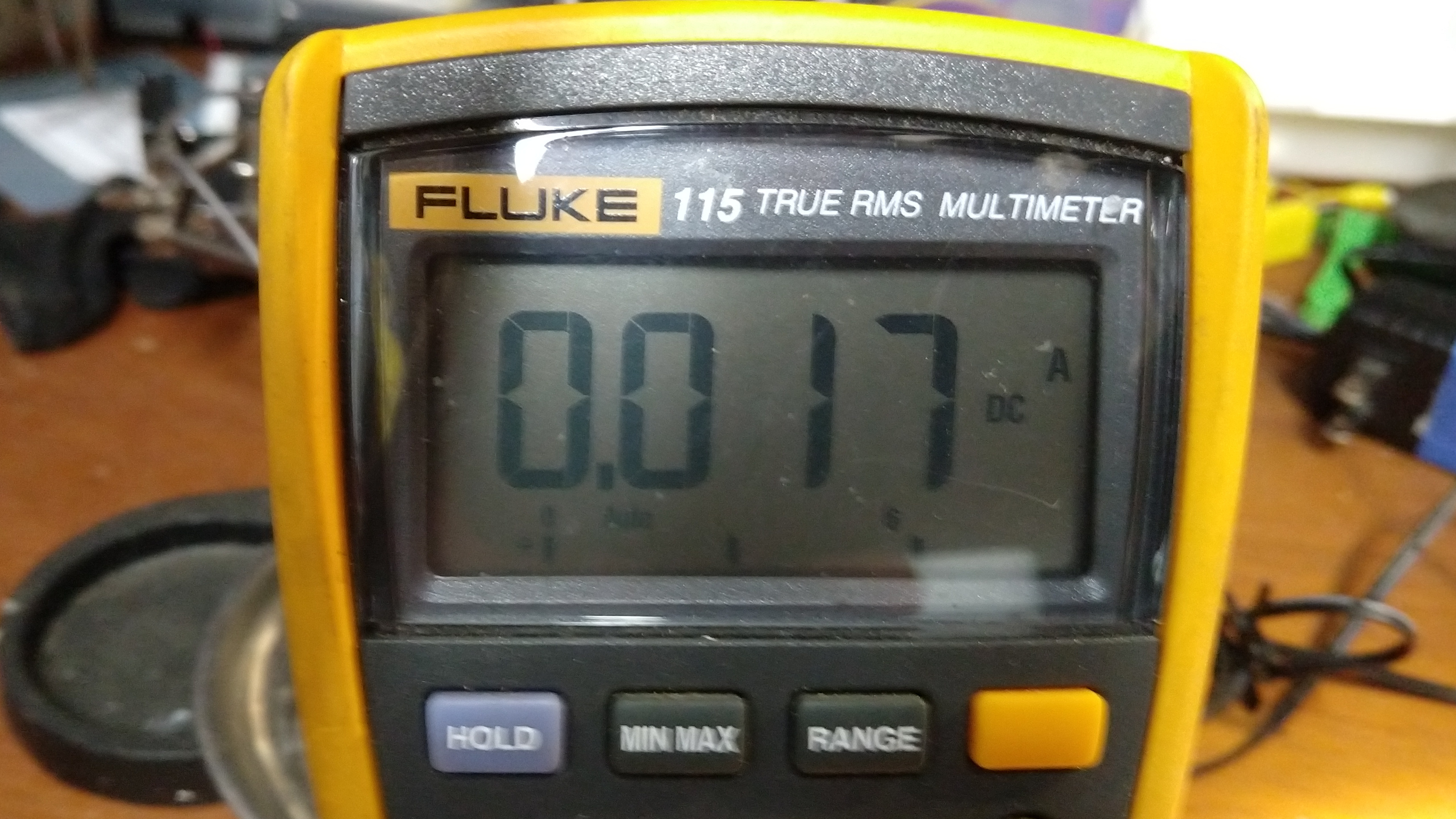
  • I de-soldered the output leg of the power regulator from the rest of the circuit, and the output voltage went up to 5 volts, which hinted that the problem might be farther into the circuit. However, when I tested how much power the regulator could provide, it would only drive 17mA into a short! (A good regulator should provide 100 or 150 mA of power.)

  • I wasn’t sure if the resistor on the input leg was limiting the current that much, so I took the whole thing out and tried powering the regulator directly by bypassing the resistor, and it had the same low output current issue.
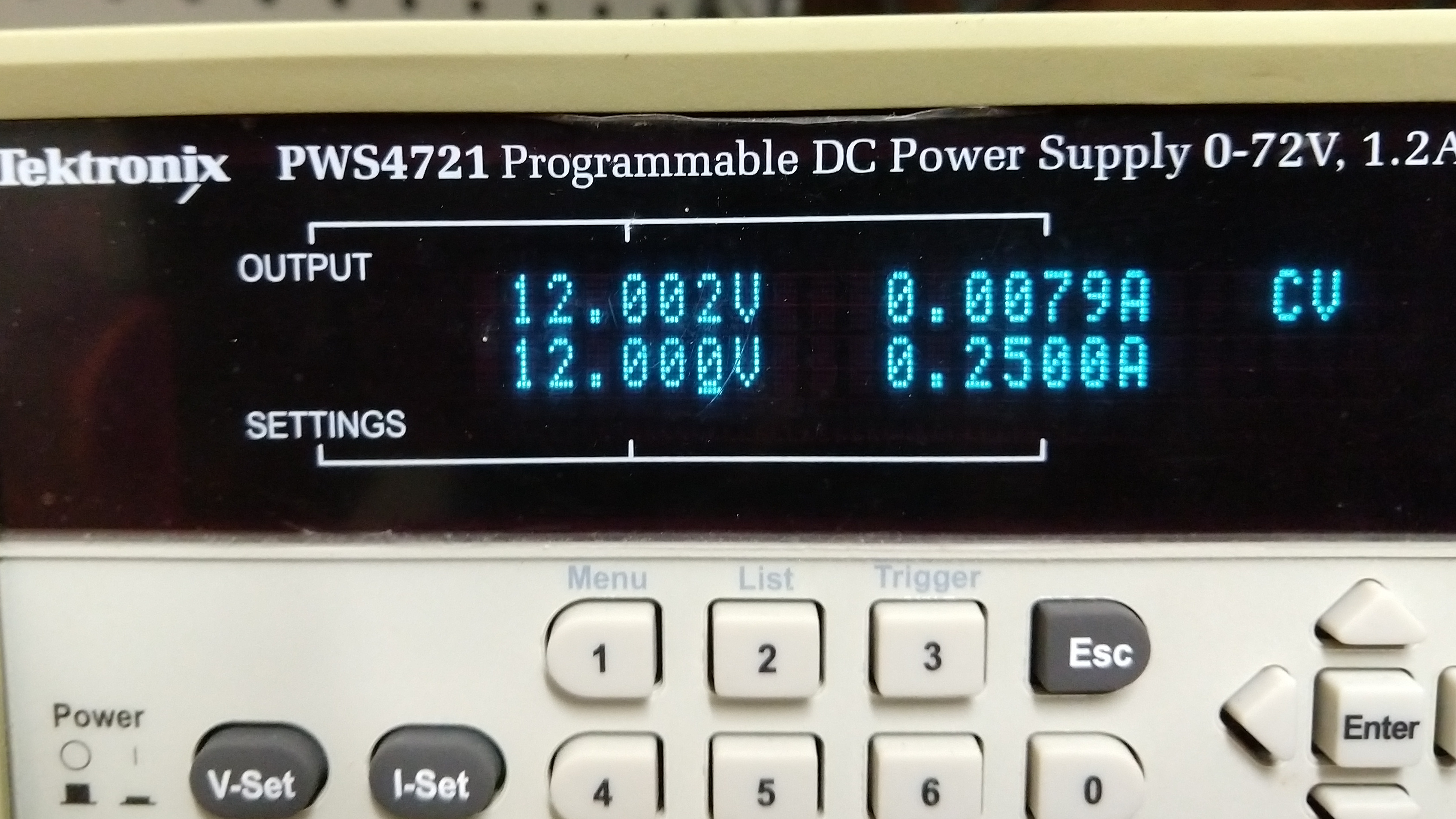
  • So, time for a new 78L05 power regulator. This is a VERY common 5 volt regulator, and I happened to have one in-stock, which I soldered back into the circuit. I considered leaving in the input resistor (520 ohm), but decided against it, as the original circuit schematic obviously didn’t have that part, and according to the spec sheet, a 78L05 should be able to go from 12v down to 5v without problems. I measured the idle current draw of the entire motor unit afterwards, and it was only 8 mA, so the voltage regulator is dissipating 12-5 = 7 volts at 8mA, or 0.056 watts (5.6 mWatt) continuously, which is trivial even without a heatsink.

My suspicion is that the factory substituted an “off-brand” (or even counterfeit) 78L05 power regulator which they knew would have trouble dropping 7 volts, so they put a resistor in front of it to drop some of the voltage/power external to the power regulator, but the cheap part still failed.   I’m hopeful that I have now replaced all of the parts that are likely to fail in this unit, and perhaps it will work well for me in the future.


Do you need to clean your solar panels in Florida?

Living in Florida, we get a lot of rain that does a good job of keeping our solar panels mostly clean. To see if extra scrubbing was needed, I cleaned 1/2 of my solar panels after they had been installed for 11 months using a scrubbing brush and dish detergent.

The panels that I cleaned went up in power production by an average of 0.11 kWh/month. [0.11 kWh * 36 panels * 12 months = 47.52 kWh of extra power over an entire year…assuming the cleaning effect persists after the first month.] So this is a very small amount of power (about $6 worth at 13 cents per kWh.) in return for an hour of scrubbing. [And this assumes that the cleaning benefit lasts for a full year, which may not be the case.]


I would suggest only scrubbing your (Florida) panels every few years unless you notice a drop in performance.


You can download my data and simplistic analysis in the attached open document spreadsheet: SolarPanelCleaningExperiment


Banshee sailboat mast/boom storage and sun/rain cover mount


I cut some plywood to fit the front and back of the Banshee sailboat with notches to hold the two part mast and boom in a triangular shape, so that they would support a rain/sun cover to allow it to shed water.   Even though the wood would be protected under the cover, I gave it a good coat of exterior paint. I also used 100% silicon along the bottom in an effort to keep it from sticking to the boat (which will matter more once I re-paint the boat….which is in the long term planing horizon now that it’s somewhat protected from the elements).

The   boat cover that I bought was the shortest available (14-16′) , and it almost fits (it hangs down a little on the back) and so far it appears to be of a good quality given the $50 price point: MSC Heavy Duty 300D Marine Grade Polyester Canvas Trailerable Waterproof Boat Cover, Pacific Blue,Fits V-Hull,Tri-Hull, Runabout Boat Cover,Full Size Boat Cover Purchased From Amazon.   I’m using the “A” model — Length:14″²-16″² Beam width: up to 68″³ (Fit V-hull runabout boats with beam width to 68″)

Cover longevity update: 22 months in, the cover has turned from a blue to a gray where exposed to the sun. It has a few small rips where it caught protruding hardware on the masts before I learned to put gaffers tape over them (and cover the end of the masts with spraypaint can lids), but I expect to be able to get 2-3 seasons out of this cover.

Here are some photos of the plywood:

Continue reading

Nissan Leaf 12 volt accessory battery replacement

My wife came home one night and told me that when she had started up her Leaf for the drive home it “acted wonky” with lots of warning lights on the dash, and the brake pedal went to the floor without actually keeping the leaf from inching out of the parking space she was in.   This sounded like the 12 volt accessory battery was no longer holding a charge and was in a low voltage state (which the electronics in the car really don’t like!). This happens when the battery ages, and Nissan Leaf’s are notorious for going through 12 volt accessory batteries quickly.   (Even though the batteries don’t need to provide a lot of cold cranking amps to turn over an engine, the car electronics draw a lot of power, and the main power distribution unit will re-charge the battery at a high amp rate when the car is on. They are also a relatively small sub-compact size (Group Size 51R).   The car is 4 years old, so I figured it was about time for the OEM battery to be replaced.

When I went to examine the battery under the hood, I realized that it needed to be replaced sooner rather than later. It’s never a good sign when the special blue power crystals escape from the positive terminal lug, or battery acid eats the paint off of your battery hold down bar…

So, after spraying foaming battery acid neutralizer all over the place, I re-painted the battery hold down strap and bought a Duralast Platinum 51R AGM (Absorbent Glass Mat) battery at AutoZone that comes with a 3 year replacement warranty.   (It was   cheaper than the yellow top Optima AGM battery that is widely recommended for the Leaf, and the warranty period was the same.)

People online have said that AGM’s work better with the high current charge rate provided by the leaf’s power distribution center, and I figure that being sealed they would be less likely to vent acid over other parts of the car. I could have gone with the $70 battery that came with a 3 month warranty, but I figured that the Leaf is hard enough on it’s accessory battery that I’d better pay for the good one.

So far the maintenance needs of the Leaf have been relatively small, and this is the first major item that needed to be replaced. (New tires are coming up soon.) Other than this   battery replacement, I’ve bought new wiper blades, replaced the cabin air filter, refilled the wiper fluid and rotated the tires.

Mounting Ring Floodlight Cam under an eave

I’ve been happy with my Ring Doorbell camera, and when one of our motion lights stopped working, I decided I wanted to use the Ring motion detecting Floodlight Camera to replace it. The only problem is that the Ring Floodlight Camera is designed to be wall mounted (about 8′ high) and Ring specifically says it can’t be mounted under an eave. Challenge accepted.

As It turns out, you CAN mount a ring floodlight cam under an eave, but unless your eve is flat the camera part doesn’t have quite enough play in the provided ball joint.   (My eve follows the upward slope of my roof.) To fix this, you need to loosen the retaining screw, pop the camera unit out of the ball joint, and then grind a notch that will allow it to swivel upwards (formerly downwards) just a bit more.

The end result looks like this:

Here you can see the notch I ground out of the ball joint:


I used an angle grinder with a grinding wheel, but the plastic is soft, so you could do it with a rotary tool or even with a file by hand if you had a lot of extra time. Note the masking tape to make sure the camera cable stayed well out of the way of the grinding wheel.

There is an internal square tab inside the ball joint, which also has to be filed down (I used a hand file for this one):

After this small modification to the ball joint, there was plenty of flexibility to aim the camera exactly where I wanted it and have the bottom of the motion sensing pod level with the ground. Of course, you will need to rotate the lights so they are not “upside down”, so the “rain shields” are correctly on the top.   [Note that the camera part is shipped “upside down” in the box, and normally you would need to flip it over when wall mounting, so you can omit that step.]

I am lucky, in that I have a low roof, so that the angle of the camera is still right around where it should be for capturing good images of faces. If you had a two story house, mounting a camera under the eave wouldn’t give you a very good angle.

Does this modification void the warranty? Possibly. If the device fails due to this modification, it would certainly void the warranty. [For example, if the camera unit falls out and breaks after I modify the ball joint designed to hold it.]   However, if the camera unit were to fail due due to an electronic or software problem completely unrelated to the modified ball joint, the Magnuson-Moss Warranty Act could give me legal standing to insist that Ring replace/repair the camera unit because its failure was unrelated to my modification.   [I’m hoping the situation doesn’t come up….I made sure to test the floodlight camera before I broke out my angle grinder to make sure everything was working right before I started hacking on the ball joint.]

Banshee sailboat rudder & tiller rigging

This is my new (to me) Banshee sailing dinghy. She is 13 feet overall, and cat rigged, which means she only has a single sail behind the main mast, with no head sail. This rudder and tiller doesn’t look exactly like that shown in photos online of other Banshee boats, so it may be a later retrofit.

This is how I rigged up the rudder and tiller. All of the attachment points were already there when I got the boat, but I added two bungee cords and an up-haul line. I have no idea if this is the “official” method, but it seems to work for me.

First, I wrapped a 24″ bungee around the tiller and secured it to this forward eye strap with a chain link and then attached it to these pre-existing eye straps on the inside of the transom. This gives an automatic “return to center” action for the rudder.

I used a 42″ yellow bungee cord wrapped in the middle around an existing bolt
in the front of the rudder to pull and keep the rudder down, while at the
same time, allowing it to rotate backwards if ran aground.

I attach the ends to this front eye strap when under way, or can move them
to this rear eye strap to make the rudder easier to lift.

I used a 1/8″ line tied to an existing hole in the back and of the rudder and routed around the tiller to a bottom mounted jam cleat to raise the rudder. It’s certainly possible that this jam cleat is really intended for a down-haul line, and not an up-haul line, as it’s on the bottom of the tiller.

So, that’s what I’ve done, it works for me, but feel free to leave a comment if I’ve completely messed things up.

Philips Norelco QT4085 beard trimmer disassembly and battery replacement

My trusty (yet old) beard trimmer has needed to be plugged in to use for a long while now, but the batteries finally degraded so much (I suspect they were a direct short) that even plugging it into its charger failed to make it work. So, I took it apart and replaced the batteries. (They needed it, I believe they were from 2001.)

This video distills what I learned (the hard way) about the proper order of operations for disassembling this model to get to the battery to replace it.

Tektronix PWS4721 power supply teardown / diagnostics / repair

I broke my PWS4721 power supply by connecting it to a battery and driving current back into it. (I don’t remember if I reversed the polarity, or just had the output voltage lower than the battery voltage.) The end result was that the power supply had it’s output shorted internally, so that the output voltage was always near zero, and the current was right at the maximum current limit but no power was coming out of the front (or back) connections.

The broken component turned out to be Diode D408 on the main circuit board right in front of the power output header. It appears to be a reverse polarity protection diode, so it’s likely that I accidentally reversed the leads when connecting to the battery (all I remember is the spark). This diode is a 1N5408 (general purpose 1000 volt 3 amp diode) which I was able to replace for $0.40 (Although my total cost was closer to $10, as I ended up buying 10 of them just to have a few more sitting around if needed, and shipping cost me $4.33 from Digikey.) The only specialized tool I needed was a Trox-10 (t-10) screwdriver to remove the security (star) screws from the factory maintenance port so I could remove the back panel.

Of course, I had to disassemble the entire unit to get to the bottom of this circuit board to make de-soldering and diagnosis easier.   The output power rails were shorted before I removed the diode, and were NOT shorted after I removed it, and the diode had failed shorted, conducting in both directions.

In retrospect, I could have probably desoldered the diode in place from the top of the circuit board (the long lead would have been easy, and since the diode was already ruined, I could have heated up the body and pulled the whole thing out from the top and then replaced it without removing the entire circuit board. But, at the time, I wanted access to the rest of the circuit board just in case the diode wasn’t the (only) problem.

You know it’s a high quality piece of equipment because in addition to checking that it worked, they let it burn in to find out if any parts were going to fail quickly, and then calibrated it!

If you want to see how to tear down a PWS4721 and what is inside, here is the video:


And a few photos of the main board with heatsync and top logic board:


NES Classic 500 in one game console controller pinout

I had to repair the cable on one of those “500 in one classic game consoles” that look like a mini Nintendo Entertainment System (NES) but don’t actually say the “Nintendo” trademark on them anywhere.
An example can be found on Amazon here:
https://amzn.to/2JBgzSS

The order of the wires inside the controller on the PCB (NES01-JOYV1.1) is (from left to right): orange(red), yellow, blue, brown, white

The pinout for the wire colors at the end of the cable is as follows:

My Glowforge Lid Handle Fell off!

I went to use my Glowforge laser cutter today, and when I tried to open the lid the handle fell right off onto the floor!   This wasn’t the first failure I was expecting from this device! (I figured the laser tube would die, or something to do with the electronics would fail…but no, the glue used to attach this metal and plastic handle piece to the safety glass that makes up the lid just let go!)

Unfortunately, the lid handle has some wires running to it (for the “lid closed” sensor I assume) and now my glowforge thinks the lid is open all the time and won’t do anything. The lid handle has two wires on each side that normally plug into sockets on the end of the LED light bars on the left and right side of the lid. The one on the left nicely unplugged itself when the lid fell, but the one on the right pulled the socket off of the lightbar, and would require at a minimum some soldering to reattach the socket to the light bar PCB.

As my warranty has expired, Glowforge offered to charge me $200 for round trip shipping of the unit to and from their repair location, and after they receive the unit they will tell me how much a repair would cost (if a repair is possible.) The customer service email said that they couldn’t repair the part in the field as some of the parts that would need to be replaced require calibration which they can’t do in the field. (I assume they were speaking about the camera mounted on the underside of the lid. They may have mistakenly thought that the lid had separated from the hinge in the back, but I guess if they replace the lid entirely instead of just attaching the handle again they would need to re-calibrate that camera to the rest of the laser cutter.)

Since a brand new cheap Chinese K40 laser cutter only costs $400-500, I decided to attempt this repair on my own. After laying out a moving blanket to protect the laser tube from errant solder drops, I was able to solder the socket back in place with only a few scorch marks on the shiny white PCB.


I plugged the lid closed sensors back into the sockets, held the handle onto the lid while closing it (the weight of the lid keeps the handle in place when closed) and my Glowforge operated as normal!   The only thing remaining is to determine the right type of adhesive to permanently re-attach the handle to the lid. Glowforge support understandably didn’t want to go on record with a specific recommendation for this unauthorized DIY repair, so I went with JB Weld (Clear) 2 part 5 minute epoxy. So far, the handle remains attached to the underside of the glass lid.

December 2020 Update: Handle still attached to glass lid. However, the other end of the lid detached from the hinge side of the Glowforge.