COVID-19 / Coronavirus Resources / Reading List

Stuck at home, I’ve spent too much time reading the internet about the Coronavirus. Below are the most useful resources I have found for understanding what is going on and what is likely to come in the future.

If you only have 8 minutes, this video is the best overview I’ve found:

https://www.youtube.com/watch?&v=BtN-goy9VOY

Status Tracking

Why Social Distancing?

What needs to improve?

Actions you should take

About Covid-19 / Coronavirus

Timeline Back to Normal

Humor

Older links that are still relevant:


Making Thunderbird send messages in the background (like Outlook)

My work recently changed over to using Office365.com for their email. As long as Office365 supports IMAP and SMTP (it does) I don’t mind so much, as I can continue to use Thunderbird on my desktop to access my email.

However, because the mail servers are no longer located “on-campus” the lag to the SMTP server is much more noticeable than before. When I pressed the “Send” button, Thunderbird would sit there for 20 seconds with a progress bar sending the mail, interrupting my flow of email processing much more noticeably than when the server was hosted on the same network.

So I tweaked a few advanced settings in Thunderbird by going into Thunderbird Preferences (Edit->Preferences), clicking the “Advanced” tab, then selecting the “config editor” button and promising to be careful. [Newer versions of Thunderbird have these options under the tools -> Options menu. ]

mailnews.show_send_progress false
mailnews.sendInBackground true
offline.send.unsent_messages 1

Telling thunderbird to not show the progress indicator only hides the dialog, but the compose window still sits up on your screen (with no visible indicator of what it’s doing) until the mail is sent, so you also need to turn on “sendInBackground” to make the compose window disapear immediately after you press send.

This makes the message go immediately to your Local Folders -> Outbox, but DOES NOT SEND IT, until you select File -> Send Unsent Messages. Hence the “offline.send.unsent_messages 1” which tells Thunderbird to send unsent messages (from Folders -> Outbox) whenever it can. It still takes 20-30 seconds for the message to be sent, but it is done in the background now.

How to build custom length high current cables

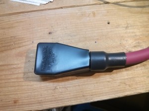
IMG_20151025_203133

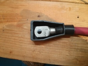
IMG_20151025_202930

When wiring up an electric vehicle traction pack battery, an off-grid battery backup bank, or other high current power systems, you sometimes need a cable capable of handling high-current with a custom length. If you have a few tools, it is easy to make your own by crimping terminals onto welding cable. This video shows a time-lapse overview of making such a cable:

Here is a set of links to the tools and materials I used:
Continue reading

Getting rid of extra UI elements in Google Reader!

My wife complained about all of the extra stuff at the top of Google reader. You know, the links to all of the other Google products in the black bar, the humongously big “Search Reader” bar and Google logo. I had never really minded them before, but it does take up around 150 pixels before you get down to your actual content!

Default Google Reader UI with lots of stuff at the top

So I searched around and found out that other people also dislike all the extra clutter and have designed scripts that will allow you to give the Google User Interface a haircut. If you are using Mozilla firefox, you can install the Stylish plugin and then the Google Reader Absolutely Compact style to get the following effect:

Google Reader after Stylish script to give the UI a haircut

Of course, the Stylish modification is a “one size fits all” super compact view. I actually like having access to the “Entry Actions” (keep unread, Email link, Plus One, etc…), so I ended up using the Google Reader Absolutely Customizable script for the Greasemonkey add-on, as it allows you to fully customize which elements are shown/hidden from within the Google Reader GUI (click on the “Subscriptions” drop down menu, select “Customize…” at the bottom.). Here is my final view of Google Reader:

Final customized google reader view

A List of Bubble Displays

I’m going to be building a bubble display. So, here is my collection of related work:

  • The Information Percolator ( video ) – 32 tubes, 40mm in diameter. Overall display size 1.4m (wide) by 1.2m (tall). Approximately 25 separate “bubbles” can fit in a 1.2m tall tube. Water was used as the medium. 40mm tubes worked “better” than 20mm or 25mm tubes. Used an aquarium air-stone as the diffuser at the bottom of each tube. Each tube was also connected to all other tubes and a drain so that the water level would be equalized between them, and the water could be drained. Each tube was powered by an aquarium air pump controlled by a solid state relay. Each tube had it’s own check valve (to keep the water from flowing into the pump when turned off) and an airflow adjustment valve (to adjust for variations between different air pumps). Timing of air release is accurate to a few milliseconds, but only 25ms accuracy was needed. Note that the time a particular tube was “off” modifies how much water needs to be expelled from the system before air will flow, so sometimes 50ms is needed to produce a bubble.
  • Bubble Display (video) by Jon Bennett, Sahinaz Safari, and Gouting (Jane) Chang at the University of Waterloo is very well documented. It used glycerin as the medium and non-defused bubbles for a cleaner look and a slower scroll rate. 24 valves spaced 4.7 cm apart with baffles to keep the bubbles separated. They used a high pressure compressor with a regulator to output 12psi air at each valve. They had air pressure “accumulators” to provide a buffer so multiple valves firing at once wouldn’t reduce the pressure too much. They also had a manifold (possibly with valves to modify the air flow to each valve?) A check valve (clippard MCV-1AB) kept the glycerin from flowing back into the system. They eventually selected Parker A005-C23-2P valves that were operated for 10-20 miliseconds “on-times” (50 microsecond timing resolution was required). His suggestion was to use even smaller valves. Overall cost was large, due to the use of “full-price” pneumatic components.
  • The bubble Screen ( Video ) Bubble Screen by Beta Tank – The website was down when I accessed it, so not many details currently available.
  • Matt Bell has been working on a small bubble display and making steady progress improving it. His display uses solenoid operated valves to inject the bubbles, and his improved version uses individual tubes for each column.
  • Update: PipeDream III – I missed this one in my initial roundup, but it was mentioned in the comments of a hack-a-day post. Uses small tubing so that the bubbles don’t “catch up” to previous bubbles and solenoids to add the air.
  • Update: Bulb Bubble Display (video: video ) – I believe this bubble display was completed in 2013 (after mine) and I found it via a post to my bubble displays project video page on YouTube. It uses 64 tubes, with compressed air injection via valves controlled via shift registers. The tubes are part of a “garden partition” or tuftex type plastic wall that is already divided into cavities. I LOVE the idea of using that for the tubes, as it eliminates a lot of the tube construction / allignment issues (although I imagine you still have to seal the bottom well… They used silicon molded on the bottom of the “wall”).
  • If I missed your favorite bubble display, send me a URL linking to some useful information!

Not bubble displays, but related, waterfall displays like this one, this one, or this one are also cool, but run a lot faster, and in the opposite direction.

My thoughts:
Water for a fast rising bubble, glycerin for a slow rising bubble. Air-stones for a diffused look, or a tube for solid bubbles (which look better in glycerin)…overall the choices appear to be an aesthetic one.

Everybody who starts off with a single tank eventually goes to a series of tubes or baffles to keep the bubbles from interacting with each other (drag and drafting effects), unless they space the bubble generators out very far apart.

Carefully controlling the amount of air that is released appears to be the hardest aspect of the project. Aquarium pumps appear to have less control than solenoid operated pneumatic valves.

Common problems were leaks and difficulties sealing tank seams and mounting issues.

The biggest cost appears to be the hardware for each tube that produces the actual bubbles, with pneumatic (solenoid operated air valves) being more expensive than aquarium air pumps. I don’t plan on paying retail for my air pumps or electrically operated valves. Now, if only I could find a surplus supplier of check valves….

Most of these bubble displays were relatively short. Seeing as how you get the vertical axis “for free”, it seems like you should make your bubble display as high as your tank/tube allows. At a minimum, a six-foot height sounds like a good starting point.

Robot Pool Skimmer Propulsion Test

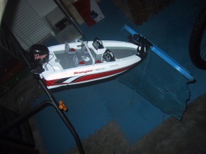
One of my long term projects is to build a robot pool skimmer. It will probably turn out to look even more ghetto than this pool net taped to the front of an RC boat:
Radio Controlled boat with pool net taped to the front

The point of this exercise was to test the thrust of the motors on one of the boats I purchased as a donor hull. It is able to push a normal sized leaf net around the pool (slowly).
RC boat moving in pool
Continue reading

Adventures with a boost converter

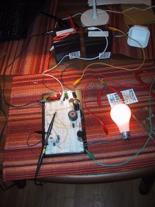
Breadboard with electronic components and wires, lighting up a lightbulb
A boost converter is a dynamic electronic circuit that can “boost” a lower voltage up to a higher voltage. Current is of course reduced in the process, but if you design it right you only lose 5-25% of the overall power. I am in the process of building one that will convert the approximately 70 volt nominal output provided by my solar panels into 125-140 volts that will charge my trucks batteries. I also plan on adding a bit of maximum power point tracking and battery charge regulation to the control logic, making it a MPPT solar boost converting charge controller. Why do I have all of these wires and parts scattered across the dining room table? Because the market does not sell what I need. (Believe me, I’ve looked.) So I have decided to build what I need.

Not being an electrical engineer, I probably won’t be able to get 95% efficiency out of my system, but so far I’ve measured 85-90% efficiency when doubling voltage. [Test 1: 23 volts in at 0.28A for 6.44 watts, 46 volts out at 0.12A for 5.52 watts means 0.92 watts loss = 0.92/6.44 = 0.142 or 14.2% losses. Test 2: 34.8 volts in at 0.35A for 12.18 watts, 72.3 volts out at 0.15A for 10.84 watts, or -1.335 watts loss, which is 10.9% losses.]

I’m still running things off of a (relatively) low voltage and current supply (two/three 12V 5AH batteries) while getting everything working, and only boosting up to 50-72 volts when testing.

I had the circuit up to 95 volts (max of 16 watts) on the output side, but I really want to optimize it for a voltage doubling, and you lose a good amount of efficiency when going higher than a 50% duty cycle.

I have also not been able to find a commercially available boost regulating control IC that works with 100 volt inputs and produces up to 200 volt outputs. One probably exists, but digikey doesn’t appear to have it. I’m solving this problem by programming my own using a PIC micro-controller. At least the programmable nature of my controller should also allow me to add the battery charging maximum voltage/current and solar panel MPPT logic into the system. I am currently working on a single phase boost converter, but the plan is for the final system to be two phase (which basically means that I use two of them in parallel). This means that I need my single phase system to be able to support 100-175 watts maximum. Soon I’ll be moving from my 25 watt resistive load (25 watt lightbulb) to a 100 watt resistive load. Eventually, I may even borrow a 75 volt power supply and test it up to 140 volts.

While working on my boost controller, I’ve found the following reference links very useful:

I have also made a few mistakes that people making their own boost converter may want to avoid:

  1. Within reason, the higher the switching frequency the better. I started off using a PIC12F683 chip which only has a single PWM output. Because I was planning on building a two phase system, I decided to code my own PWM loop that would support two phases with a 180 degrees difference. (A fancy way of saying that they would each be ON for the same amount of time, but that while channel A’s ON time would start at the beginning of the period, channel B’s on time would END at the end of the period. If the duty cycle went above 50% they would overlap for a bit in the middle.) After spending an hour on my fancy 2 phase PWM system and testing it with some visible LED’s, I took all of the delays out of it only to find that my 8Mhz internal oscillator could only support a period of 1.5-3 kHz. Sure, it sort of worked, but you could HEAR it switch. It also required a much larger inductor for the same power. So, I switched over to using the built in PWM subsystem, which can easily hit 73 kHz while still having 5-6 bits of precision. I now plan on switching over to a PIC 16F chip which has a dual channel PWM that I THINK can do an 180 degree 2 phase signal in hardware (if I’m reading the specs correctly…)
  2. Most MOSFETs require at least a 10 volt gate signal. If you switch them with a 5volt logic signal directly from the PIC they will switch (at least mine did), but they will not carry current without burning a lot of it up as heat. I was wasting 80% of my power as heat in the MOSFET until I wired up a transistor off of a 12V rail to amplify the signal to 12 volts. I plan on using a IXDN604PI gate driver chip for my final design.

Using the Microchip PIC Kit 1 with Linux

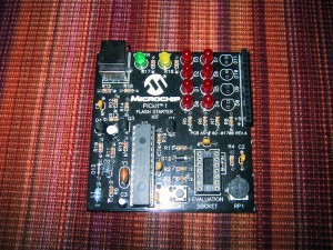
Microchip PICKit 1

The PICKit 1 is a combination programmer and development board for midrange PIC micro-controllers. In addition to being able to program FLASH pic devices, it also allows them to run and access 8 (charlieplexed) LED’s, a pushbutton switch, and a potentiometer. It’s a great little board for learning the basic of micrcontroller programing, but unfortunately it is not supported by Microchip’s new MPLAB X software (that is written in Java, and supports Linux/Mac in addition to Windows).

You CAN however use the PICKit 1 under linux. The piclab software is supposed to support it (I have not tested this). I use version 1.6 of the PicKit1 flash usb programmer for unix. Even the newest 1.6 version reports checksum errors after writing the hex file, but it does work correctly.

To make it work as an external program in MPLABX I had to select the “format HEX file for download” option under the Linker so that it would not fill all 2048 flash bytes when the program was smaller than that. I am able to manually run the usb_pickit command after building to flash the code, but it’s kind of annoying, as that program has a problem verifying the checksum and reports an error every time (which is interpreted as a build failure) plus, I have to run mplab X with root permissions to be able to access my USB port.

Controlling the Cricut Personal (desktop cutter) via Linux

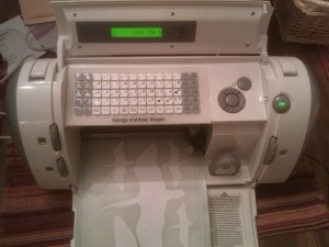
Cricut personal cutter
I caught a deal on cricut.com where they were selling their original “Cricuit Personal Cutter” (refurbished) for $49.99 ($65 with shipping). This seemed like a very good deal to me, so I bought one. By itself, the Cricuit can cut specific shapes and letters from paper (it includes a free set of shapes/letters, and you can purchase cartridges to add more). I plan on using it to cut metal foil (one of the few things you can’t cut with a laser cutter, because it is reflective) and potentially make stencils. I may also be able to use it as a plotter using special attachments for pens. (Circuit board resist markers anyone?)

To make full use of it, I wanted to be able to cut arbitrary paths from my material, which means controlling the Cricut from my computer. Continue reading

PBS Wishing – Android App to find out if a book is popular!

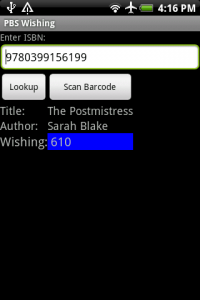
Main application screen, showing the book "Postmistress" having 610 people wishing for it. I have developed an application for Android Phones (OS version 1.5 or higher) that allows you to enter an ISBN from a book (or scan the barcode if your phone has a camera) and find out how many people are wishing for the book on PaperbackSwap.com. If a lot of people are wishing for a book, it’s a good indication that the book is popular, which may mean it is worth reading. (Or at least, if you decide you don’t like it, it will be easy to get a book credit for it on paperbackswap.com.)
Continue reading