Adding disk brakes to a bike frame without disk brake mounting holes

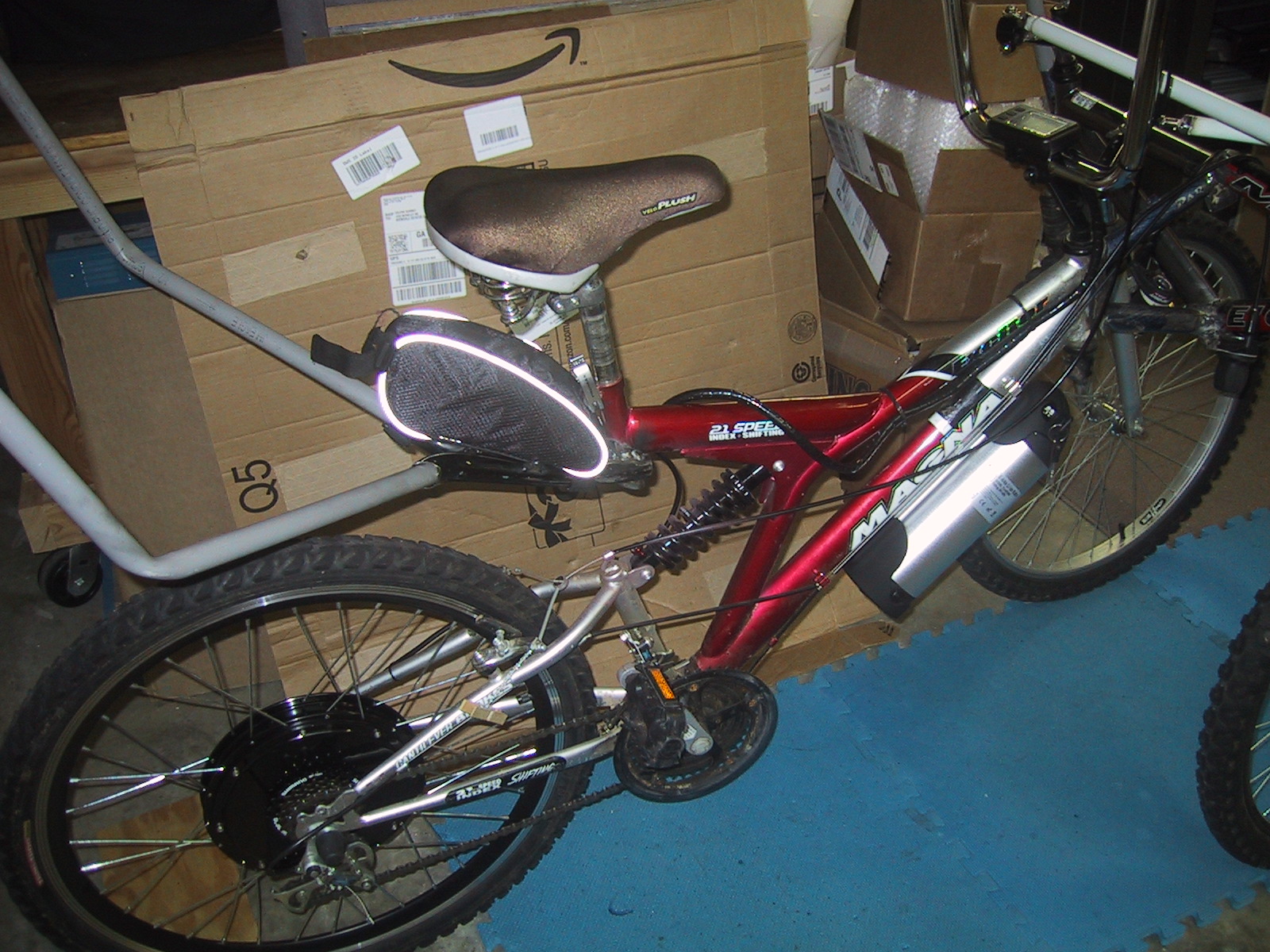
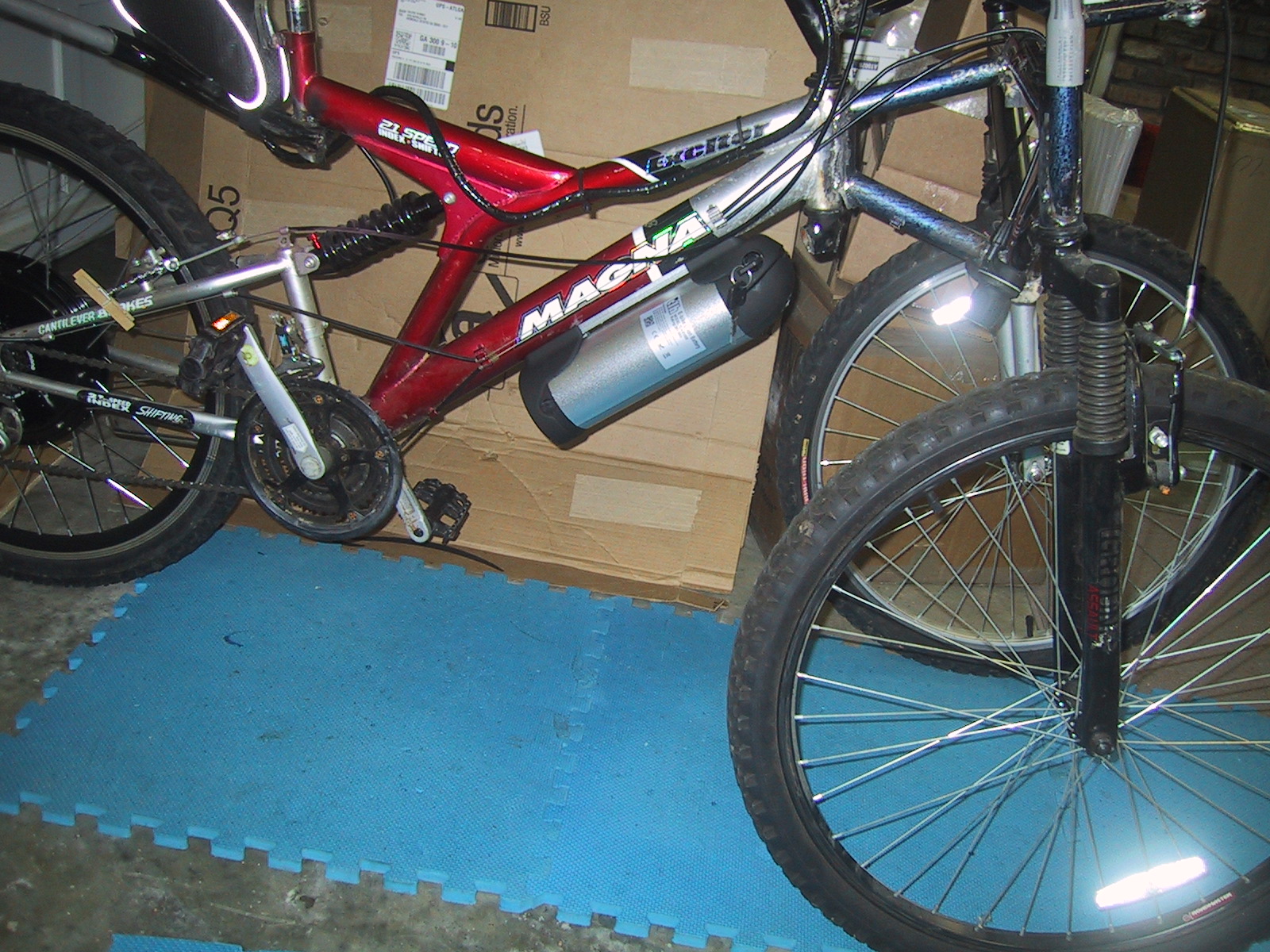
The electric hub motor I purchased had a set of six holes built in for adding a 140mm disk brake rotor. Unfortunately, the bike frame I had used was not set up to mount a disk brake caliper.

rotor_installed

I purchased the cheapest cable actuated disk brake caliper and rotor set I could find on ebay ($50) and then had to figure out how to mount the caliper. After a bit of thought, I eventually decided to keep it classy and not weld the entire thing directly to the bike frame.

Disk brake calipers are mounted using two screws, hopefully with lock washers to make sure they don’t come out. M6 SHCS (Socket Head Cap Screw), typically 1.0 thread pitch and 18mm long)

Although my bike frame did not have built-in holes for a disk brake caliper, it did have some threaded M6 holes for other purposes (racks/mudguards, etc..), so I could use one of those, and only had to add a 2nd mounting hole at exactly the right place.

hey_look_m6hole

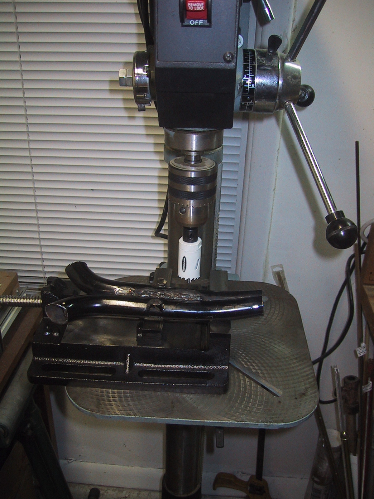
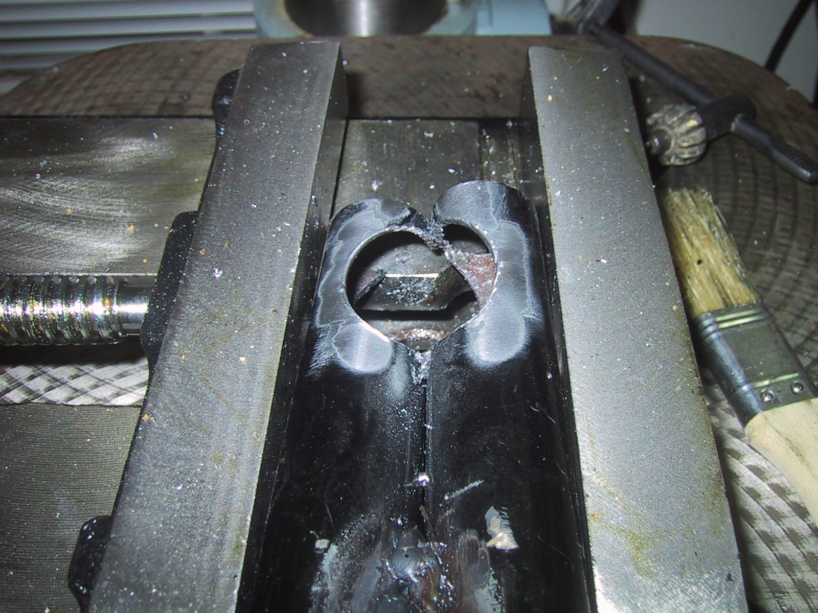
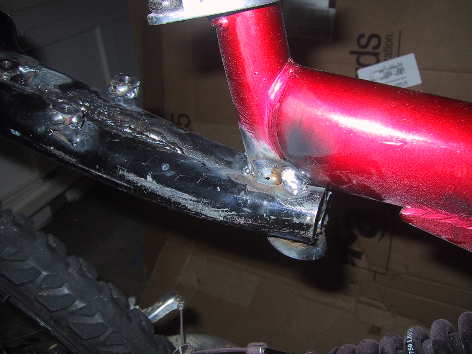
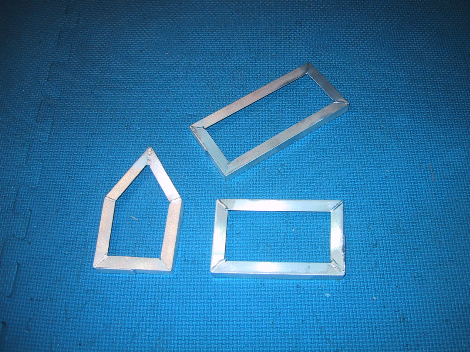
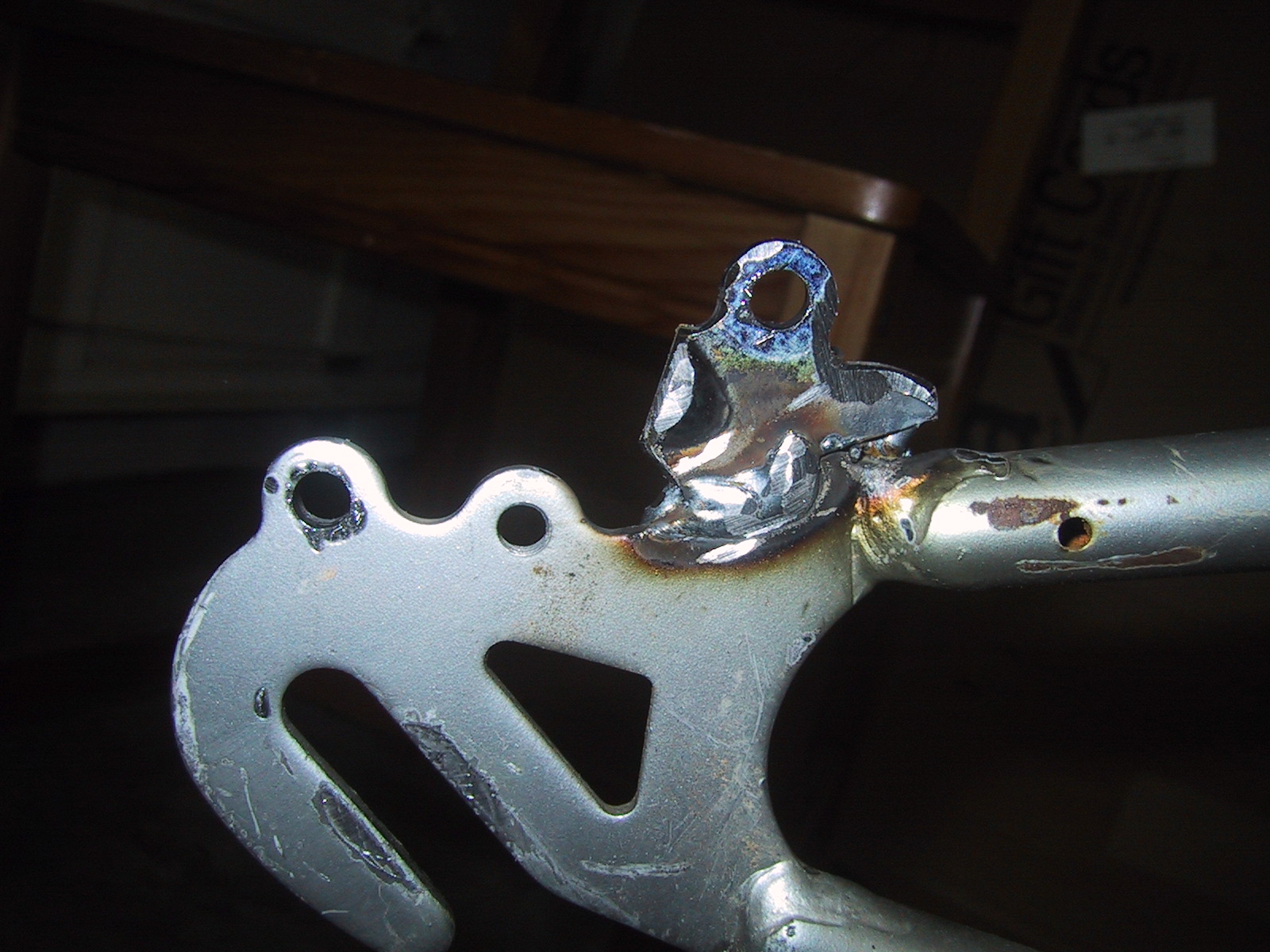
From chopping apart a lot of bike frames, I had some spare steel, and one of the spare front forks also had an M6 hole tapped into it, so I didn’t even have to drill and tap the 2nd hole. I used a cut-off wheel on an angle grinder to liberate the hole and surrounding steel, then screwed it to the 2nd hole in the caliper, using the caliper body itself to hold the steel piece in place while I welded it. (The caliper also has two screws that adjust the body slightly, so the weld doesn’t have to be 100% perfect…)

ready_to_weld2

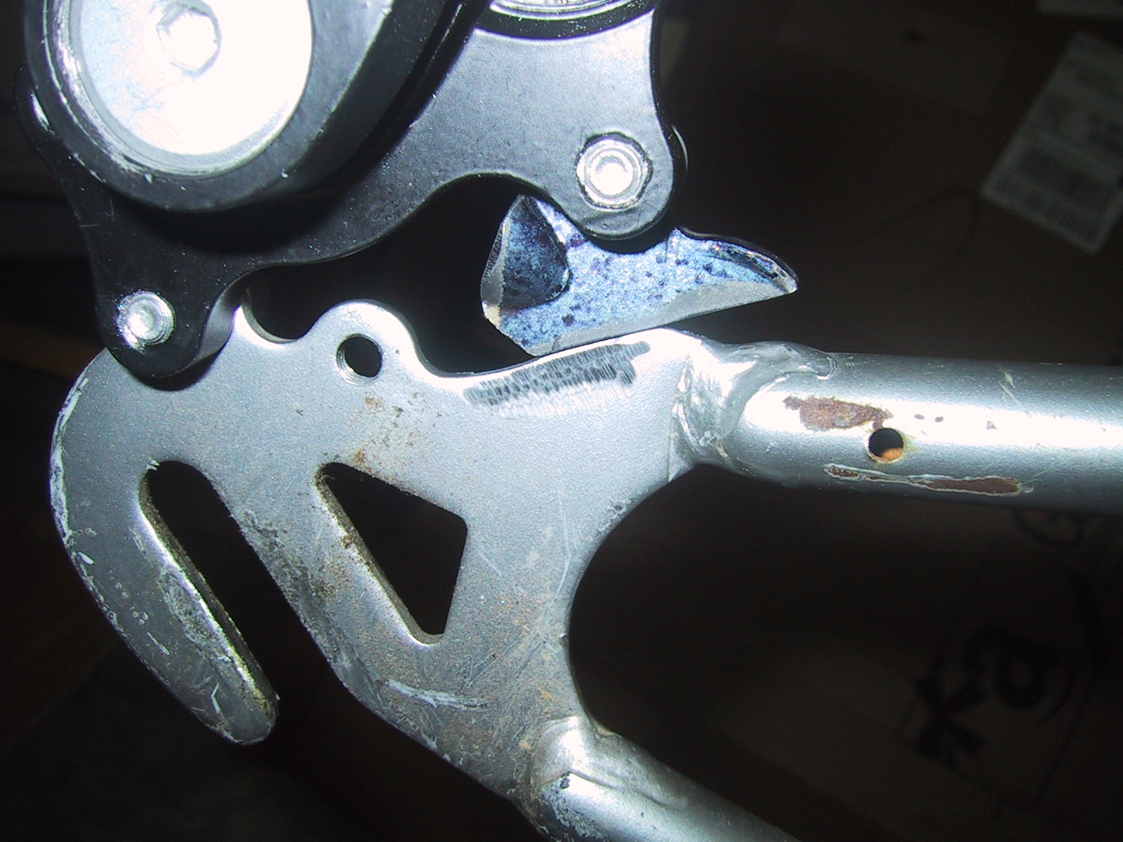
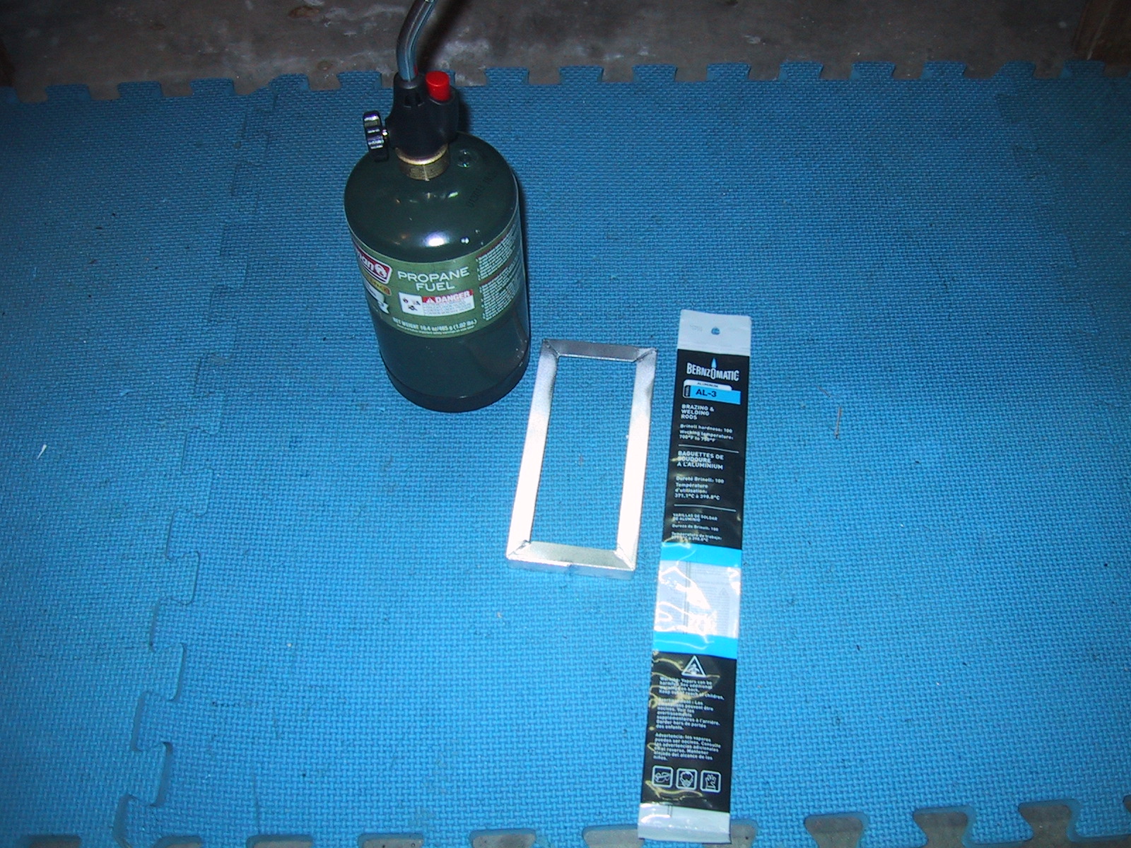
Getting the small piece of steel, and cleaning off all the excess paint to get the parts ready to weld took a lot longer than actually doing the small weld. (I could have brazed the two together, but since I have the welder just sitting there, and the welded joint will be stronger, always important for brakes…)

welded_on

Of course, because the brake caliper itself has M6 threaded holes, you don’t want the holes on the frame to ALSO be threaded (because then you can’t use the screws to tighten the caliper to the frame of the bike effectively) so after I had the holes positioned where I wanted them, I used a drill bit to ream the threads out of the holes on the frame. (N.B….never use a drill bit as a reamer…unless you don’t have a reamer….)

Franken-bike: Back Rack, Rain-cover support

rain_cover_back

I needed a place to mount the back of my rain cover on the bike. I also needed a place to place my electric motor controller bag. I solved both problems with left over bike parts. This “rack” is made out of the top half of an unused fork welded together. I cut a 1 and 1/8″ hole in it to go over the bottom of my seat down tube. I also put a few weld nuts I had laying around on the top of it, just in case I need to mount something else securely to it.

hole_saw1hole_saw2
weld_closeup

Electrifying Franken-Trike

Franken-Trike is big and heavy. And it’s only going to get bigger and heavier once I finish the rain cover. So I added an electric motor to it… Weight with motor and battery is now 80 pounds.
ebike_parts

This is a Chinese generic hub motor, controller, LCD display that includes speedometer and odometer, along with a “water bottle” style 36v 10aH Li-Ion battery pack. The motor claims to be 500 watts, and the battery claims to be able to provide 540 watts (15 amps * 36 volts), but on steep hills I have to petal a bit myself to maintain speed. On level ground it can get the bike up to a scary enough 10 mph by itself, and I expect it will fulfill its purpose of making my commute into less of a taxing workout of lugging the monster bike up the big hill…

water_bottle_battery

Fabricating Gingerbread House Cookie Cutters

three_cutters_done

One of my relatives makes a large number of gingerbread houses for all the kids (and me!) to decorate for the holidays. They have been cutting the house panels out of rolled gingerbread dough using a knife and paper templates. I volunteered to make them some custom cookie cutters, as the three panels (2x roof, 2x wall, 2x end pieces) are geometrically very simple (two rectangles, and a triangle sitting on top of a rectangle.)

alunimum_soldering_tools
I bought some 1/2″ angle aluminum at the the big box (I would have preferred 3/4″…but they didn’t stock it…), along with some aluminum “welding rod” which is really a Continue reading

OneTesla O-scope traces

I have reduced my primary to 5 turns, and using the standard 0.068 MFD tank cap, this is the general shape of my oneTesla output waveform (as captured by a scope probe hanging in the air about 3 feet away from the coil):
Screen Capture

As you can see, the primary rings up and then the secondary oscillates for quite a while afterwards.

The next three traces are running the coil at a very low power level. Depending upon where I measure between peaks on the trace, I get different frequencies:

Screen Capture
277 kHz

Screen Capture
294 kHz

Screen Capture

17.80 uS between five peaks, or 1 / (3.56 / 1000000) = 280 kHz

As the 280 is between the 277 and the 294, we’ll just say that my primary has a resonant frequency of 280 kHz, when at low power.

Next, I turned the power up a bit (around 1/3 of the way up) and got the following two measurements:

Screen Capture
263 kHz

Screen Capture
18.40 uS for 5 peaks, or 1 / (3.68 / 1000000) = 272 kHz

So my primary resonance is somewhere between 263 and 294 depending upon how I measure it, with a value of 272-280 looking to be a reasonable average.

Surprisingly, my secondary resonance measurements agreed with themselves a bit better. Here is the low power trace:
Screen Capture

And the “Mid Power” trace.
Screen Capture
(You can see the primary ringing extending out so that it becomes visible in the trace…)

In both cases, I measured 15.20 uS between 5 peaks or
1 / (3.04 / 1000000) = 329 kHz

So my ratio is currently 329 / 280 or 1.175 ( Secondary 17-18% higher than my primary).

oneTesla top breakout point for my musical Tesla coil

Since I’ll be primarily using my oneTesla to play music, I wanted a top facing breakout (so the sparks will shoot up, instead of out to the side). Also, I wanted something more professional looking than a stick of metal taped to the top of the toroid. Here is the final product on the top of my toroid:

You can visit [ this post ] to see a video of it in action.
I used the lathe to get the general shape I wanted:
on_lathe

Then turned it to even up the 15 degree angle:

And this is my original 1″ diameter aluminum stock. I tapped it for the 14-20 bolt on the top of my Tesla coil that normally has a wing nut to hold the stamped toroid together, so the whole thing just screws onto the top.

Turning custom extruder parts

finished_heatsinc
jays_parts_in_front

This is my new extruder hot end. After enclosing my printer with an insulated box, I decided that I needed to drop more heat before the plastic entry side of the end of the barrel. I accomplished this by turning an extra long barrel out of brass, and a small heatsink out of aluminum to go between the heater and the Groove Mount.

You can see the barrel compared to the original part here:
original_and_replacement_part

The barrel was straightforward to turn out of a piece of 1/4″ hex stock. I put the threads on with a metric M6x1 die.
turned_hex

The HeatSink took more time, mostly because I had to cut the fins out of a 1″ diameter rod quite deeply with a cut-off tool.
inLathe1

I compressed the several hours of work on the heatsink down into a six minute video below: