Building a Monster UPS

(Or, “My UPS is bigger than yours, Na Nah Na Na Na!”)
Most consumer grade Uninterruptable Power Supplies (UPS) are designed to give you just enough time to save your work and shut down your computer, and run off of a 5 to 7 Amp Hour 12 volt battery (and because they are discharged so quickly, the pieukert effect means that you don’t get anywhere near the full 5-7 amp hour capacity).

The battery core of my UPS is a pair of two six volt GC2 deep cycle golf cart batteries rated at a 208 Ah capacity. Running a standard computer system, they will be well within their 20 hour rate curves, but as they can deliver 75 amps for 100+ minutes they can also run higher draw appliances such as a toaster oven or refrigerator if needed.
batteries

These are the same type of batteries as power my electric pickup truck, so I have a ready supply of halfway-used batteries. They can also act as a backup battery for my truck if one of the traction pack batteries need replacing. In addition, if we have a freak ice storm that takes out power for multiple days, I can swap batteries into the UPS from my truck and keep the refrigerator and some lights running for a week.

Of course, to run a 15 amp (120 volt) appliance off of a 12 volt supply you need something better than a $50 harbor freight inverter. Meet the Xantex Freedom 458, an inverter/charger originally designed for RV use. It provides dual 20 and 15 amp AC circuits plus a battery charger and AC pass-through from shore power when available. This means that it operates like a true UPS, running on grid current (shore power) and keeping the batteries charged when available, and immediately switching over to inverter power from the battery bank if the grid goes down.

xantrex_freedom458

I used AWG 2 gauge cables to connect the batteries to the inverter (because I couldn’t buy AWG 1 at Walmart) which should be good to at least 180 amps continuous (at 12 volts, this is the 2000 watt max rating of the inverter, well more than I plan on running through the system.)

The most time consuming part of assembling the UPS was building an enclosure out of 2×4’s and plywood. (4x 28″, 4x 16″, 4x 9″, plus 2 shelves of 16×14.5″ and 1 top of 16×17.5″). I put the batteries on top under a removable top cover so that every few months I can unscrew a few wood screws, lift up the top, and easily water the batteries. If I expand the system to use more than 2 batteries I’ll probably invest in a tube based battery watering system.
super_UPS_plan build3_4x3

I also added casters to the bottom so that I can roll the UPS around to anywhere I want it (assuming it’s on the concrete garage floor, parking pad, driveway, or walkway).

Electric Pickup Truck: Cost of Ownership

ev_operating_costs
We have owned an electric S-10 pickup truck for the last 1008 days (2.75 years) and used it as a daily driver. It was driven most frequently to the MARTA station, a 4 mile round trip commute, but also made trips to hardware stores, the Georgia Tech Campus, and to the homes of various people who were selling furniture or other larger items on craigslist. It uses twenty (six volt lead acid) golf cart batteries for its traction pack, and they have gradually lost capacity. When brand new, I would take the truck on 20 to 25 mile trips without stressing the battery pack. Recently however, the absolute maximum range of the truck had dropped to 12-14 miles and if you actually drove it 14 miles you could watch individual batteries hitting their absolute end of their state of charge. Although it could have functioned as a “Get to the MARTA station” vehicle for another year (or two?) I decided it was time to replace the pack to be able to comfortably go to the hardware store or make an extra emergency trip without worry. I have placed 685 charge cycles on the pack, which is in line with the lifespan for lead acid golf cart batteries.

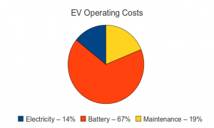
The replacement pack cost $2,171 (I gave back all but one of the used batteries for the core charge), which gives me the final piece of information needed to calculate the total cost of ownership over the last 1008 days. We spent $464 on electricity (estimated at $0.11 a KWH), $610 on maintenance, and the previously mentioned $2,171 on batteries. Obviously, the battery pack is the large cost here. In fact, the electricity cost is very small on a monthly basis, and was never more than 10-15% of our total KWH usage.

We drove a total of 4,861 miles in that timeframe, giving a cost of $0.66 a mile or $3.22 a day. This does not take into account licensing and insurance, but those costs would be exactly the same for an internal combustion engine (ICE) vehicle. If the S-10 were an ICE model, it would probably get around 20 mpg, so the fuel cost (estimating $3.50 for a gallon of gas) would be $0.175 per mile. So for 4,861 miles it would take 242.55 gallons of gas or a fuel cost of $849. This would imply that an ICE vehcile would have to have a maintenance cost of $2400 to get the same per mile cost of ownership as my EV.

Although ICE vehicles are more expensive to maintain, unless something major on the engine exploded, it looks like my hypotheical ICE S10 pickup wins the straight up cost comparison. Of course, I never had to drive out of my way to stop at a gas station, and there is the matter of 242.5 gallons of gas I didn’t use. (the lead and plastic in my batteries goes back to the factory to make new batteries)

In the interest of full disclosure, my first pack of batteries was purchased at a Sam’s Club for $1,800, so my true cost per mile is closer to $0.59. (But I used the pack replacement cost as an estimate for the cost of ownership for my next pack.)

I am hopefull that my 2nd pack (from Interstate batteries) will last longer, either because Interstate sells better batteries, or because I have learned how to care for them better. (Although I don’t think I did anything horrible to murder the first pack…)

Using a Raspberry Pi as a RepRap print host with webcam

I set up a Raspberry Pi as a print host for my RepRap (using the Pi Camera Board as a webcam to view the print status). Here are my summary steps:

  1. Install Rasberrian and update it.
  2. Configure your system to enable wifi (if used) and camera board (if used) and enable the SSH server if you want to remotely administer the pi board using the “sudo raspi-config” command (you may also want to tweak your overclocking settings here, I’m using “Moderate”)
  3. Install OctoPrint following directions here: https://github.com/foosel/OctoPrint/wiki/Setup-on-a-Raspberry-Pi-running-Raspbian
  4. If you have a camera board, you may need to update your pi firmware (sudo apt-get install rpi-update; sudo rpi-update)
  5. To get the camera board set up as a streaming webcam, install mjpg-streamer experimental version from here:
    “git clone https://github.com/jacksonliam/mjpg-streamer”
  6. You can compile it on the Pi using these instructions:
    http://www.instructables.com/id/Create-an-internet-controlled-robot-using-Livebots/step5/Get-the-webcam-streamer-for-Raspberry-Pi/ (ignoring the step to download from sourceforge.net)
  7. Install the plugins to /usr/local/lib with “sudo make install”. Copy the www directory to the same location.
  8. Start the webcam streamer: mjpg_streamer -o “/usr/local/lib/output_http.so -w /usr/local/lib/www” -i “/usr/local/lib/input_raspicam.so -x 640 -y 480”
  9. Start OctoPrint (“OctoPrint/run”)
  10. Test it by pointing your browser to your raspberry pi’s IP address, port 8080 for the mjpg-stream and port 5000 for OctoPrint
  11. When all that works, put some commands in your /etc/rc.local file to start them both up whenever your Pi boot sup. I used: su pi -c ‘/home/pi/OctoPrint/run’ & AND su pi -c ‘/usr/local/bin/mjpg_streamer -o “/usr/local/lib/output_http.so -w /usr/local/lib/www” -i “/usr/local/lib/input_raspicam.so -x 640 -y 480” ‘ &

My Thoughts: Everything works great on a wired (ethernet) connection, but my wifi adapter is performing extremely poorly for streaming video of the printer. Also, why can’t the camera board just have V4L support out of the box?

Rostock-Mini Tweaks

I brought my rostock-mini 3D printer home so that I could take it to a class, and while I had it here, I decided to update a few minor things.

highboy installed

First, I swapped out the stepper motor brackets (which also serve as the legs) with three I had designed and printed that were 20mm taller. I have a full RAMPS board under the base plate of the rostock-mini, and although it fits, the fit was “very close”. I didn’t like the fact that my stepper motor wires would touch the surface the printer was sitting on, and the limited airflow paths. This extra 20mm really helps things out, and also opens up the possibility of installing an LCD control panel under the base plate in the front. (If I can figure out how to avoid my bed leveling knobs.)

Second, I upgraded the springs on my adjustable print bed to some that were a bit taller and a bit stiffer. My overall build volume was shortened from 187mm to 185mm, but now I have a lot more range for adjustments and the bed is more rigid (while still allowing the print head to push the spring loaded bed down if it crashes horribly).

wiring harness
Third, I wrapped some plastic spiral wire harness wrap around the wires leading down to the print head, to give them a better visual appearance.

bowden tube ptc
Finally, I changed out my bowden tube from using M4 nuts to hold the tube to using screw in Push To Connect adapters. The goal was to allow me to remove the tube from either end without having to unscrew the plastic part holding the nut in place. However, the cheap PTC adapters I bought appear to be single use, in that they don’t release the tube reliably without breaking, so basically it just makes the bowden tube look slightly more professional.

Bubble Display Jr – Designs

As part of building the bubbleDisplay I made a lot of prototype tubes, nozzles, and even a small prototype display before actually committing to building the final product. This left a lot of random bubble display type parts laying around my garage. I hate throwing things out, and I wanted to have a bubble display of my own, so I’ve started to design a BubbleDisplay Jr that I can make out of leftover parts. Because I’m limited to stock on hand, I couldn’t make all of the tubes the same length (unless I wanted them all to be 9″ tall….) so I went with a Superman Memory Crystal style sculpture:

cadScreenshot

Of course, since I have a 3D printer now, I decided that printing the bracket to hold the air hoses and LED’s would be the way to go:

bracketOpenSCADSC

There….now you can’t say I don’t plan out my projects before starting them.

Bubble Display Overview Video

I spent a lot of time last summer and fall building this 62″ wide bubble display. So much time that I didn’t get a chance to edit together and post an “overview” video showing the whole thing in action. Well, here is that video. If you are looking for more build details just read all my posts tagged with “Bubbledisplay”. If you just want to sit back and watch the whole thing come together via videos, start watching my “BubbleDisplay” channel on YouTube At the beginning.

Building a Signal Generator – Paper Prototyping instrument panels

finished_box

To test the resonant frequency of a Tesla coil or other resonant circuit you need an oscilloscope (which I have) and a signal generator (which I didn’t have). I was able to follow these instructions from RM Cybernetics to build one from a 555 timer and use it to test my primary and secondary.

new_pot

The only modifications I made to the circuit was the addition of a toggle switch so that I could use two different capacitors, giving a “low” and “high” frequency range (plus a “air gap” capacitance that basically runs the 555 as a 2Mhz sine wave generator). I built the circuit on a protoboard that came with a box, and decided to use a laster cutter to make the instrument panel. To do this, I opened up Inkscape to design a control panel using vector graphics. I would print each design out and tweak it until it fit my box and circuit perfectly. I then tested various dial positions on my 10K audio scale (logarithmic) pot using my oscilloscope to mark the approximate frequency on the dial. After a few trials, I was able to laser cut the design onto a piece of 1/8″ craft plywood to get the finished product.

paper_prototying2

Yoda Bust(s)

I have been printing Yoda busts on my Rostock Mini.
yoda_on_printer

The first (small) sized one printed very well, but I had some problems when I tried scaling up to 160% size.
largeYodaHead

If you look closely, it has a small discontinuity just above the eyes. (It looks like the top of his head was sliced off and put back on slightly “off”.)
yoda_medium_slice

It looks like one of my axis lost a step, so I ran through various diagnostics (more airflow over the stepper drivers, higher current to the steppers, upgrading my slicing software, etc) and eventually the problem got worse:
lobotomized_yoda

Then I heard some squeaking from my 3D printer and started to move things around manually to isolate it and I realized that my straight rods and linear bearings were dry. The final solution was to oil my straight rod and liner bearings, although I can’t confirm that the upgrade to Slic3r didn’t also help things out. All in all, it only took four tries to get things right:

four_yodas

So now I have a large yoda head to float on my desktop levitation box:
floating_yada_head

Bubble Display Source Code & Bill of Materials

This open office / libre office / open document spreadsheet lists (most of) the parts I purchased for the bubble display, as well as the supplier part number. As some of the parts were surplus, or purchased from China via ebay, the suppliers may or may not still have them available. I didn’t keep the BOM document entirely up to date after I started to put things together, especially for several last minute runs to the hardware store, but it generally shows all of the major components.
Bubble Display BOM

This is a source code dump that includes the arduino code that I wrote for the bubble display. It’s not very nice looking, but it may help others to learn what I did on the software side of things. You’ll also need a Shifter library for the 74HC595 shift registers and a WS2801 library for the RGB serial LED string.

bubbleDisplay.ino

The “images” are encoded as individual pixels, hard coded as an array, generated by python code from simple .GIF images. Edit the image in an image editor, and then run the code to generate the C code array data.

eyes

gvuLogo

gvu20

BDPictureMaker.py

Building another Toroid

Since my first toroid was out of tune, I decided to actually follow directions this time and use an 8″ inner tube (2″ diameter) for my Toroid. I bought an 8″ inner tube and 50 yards of Aluminum Duct tape so I wouldn’t run out.

Then I went off-label and added a 4″ Big Daddio anodized aluminum personal pie pan which I’m going to try as a mounting system.
inner_tube_daddio_pie_pan

After drilling a hole in the base of the personal pie pan, I wrapped it and the inner tube with aluminum tape.

torroid2_closeup

After this picture was taken I had to extend the aluminum tape down to cover the hole in the pie pan, as the anodized aluminum pie pan was apparently not conducting. After I did that I got less than 300 ohms resistance measurement from the outside of the toroid to ground.

torroid2_on_coil

The size of this toroid is much closer to spec, although the Big Daddio pie pan holds it about 1″ higher than a straight piece of cardboard. Unfortunately, when I measured it’s resonance, I found a big signal at 340 kHz, (2.93 micro-seconds) which is even higher than my first toroid! Obviously I’m doing something wrong.