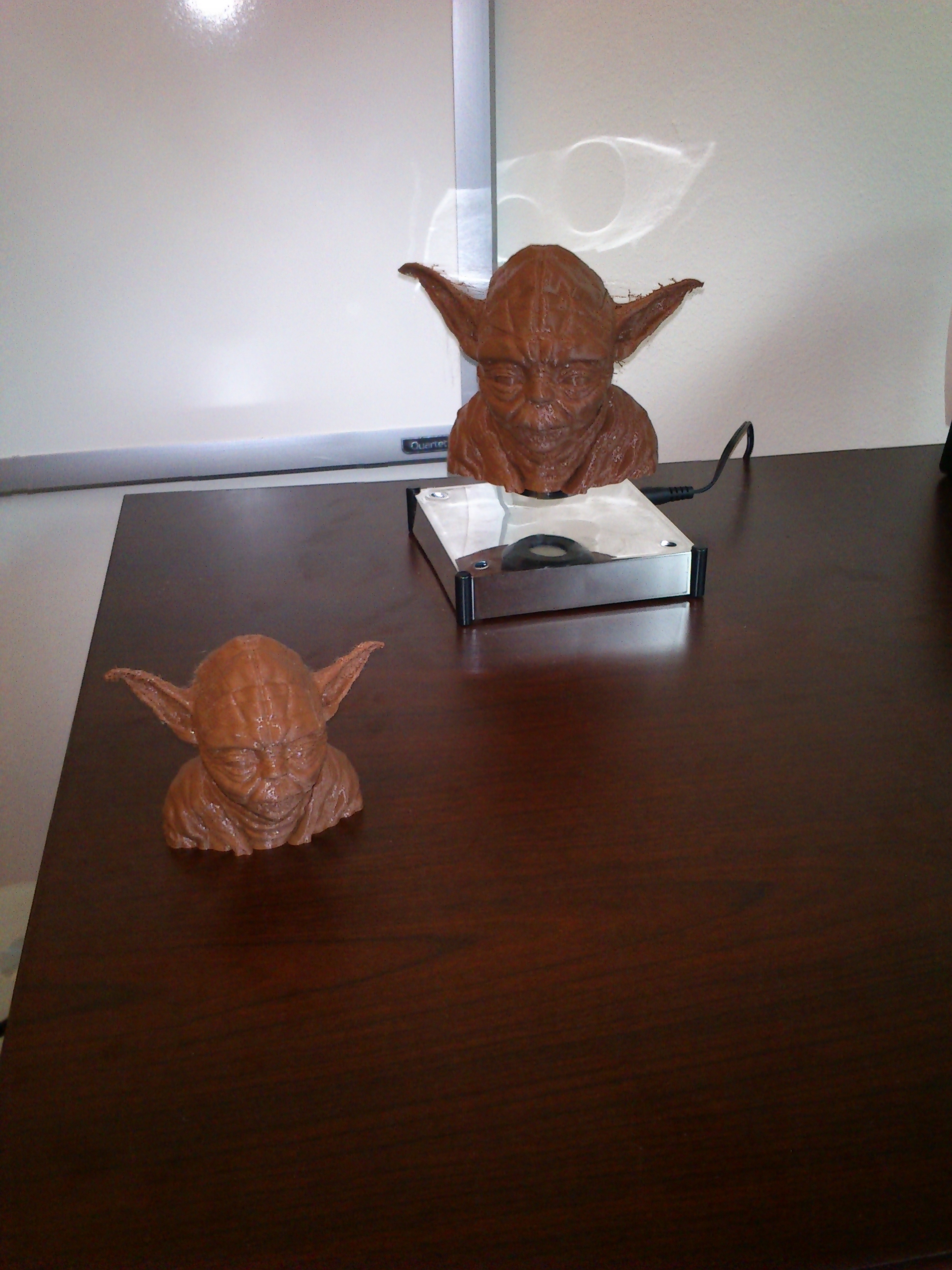
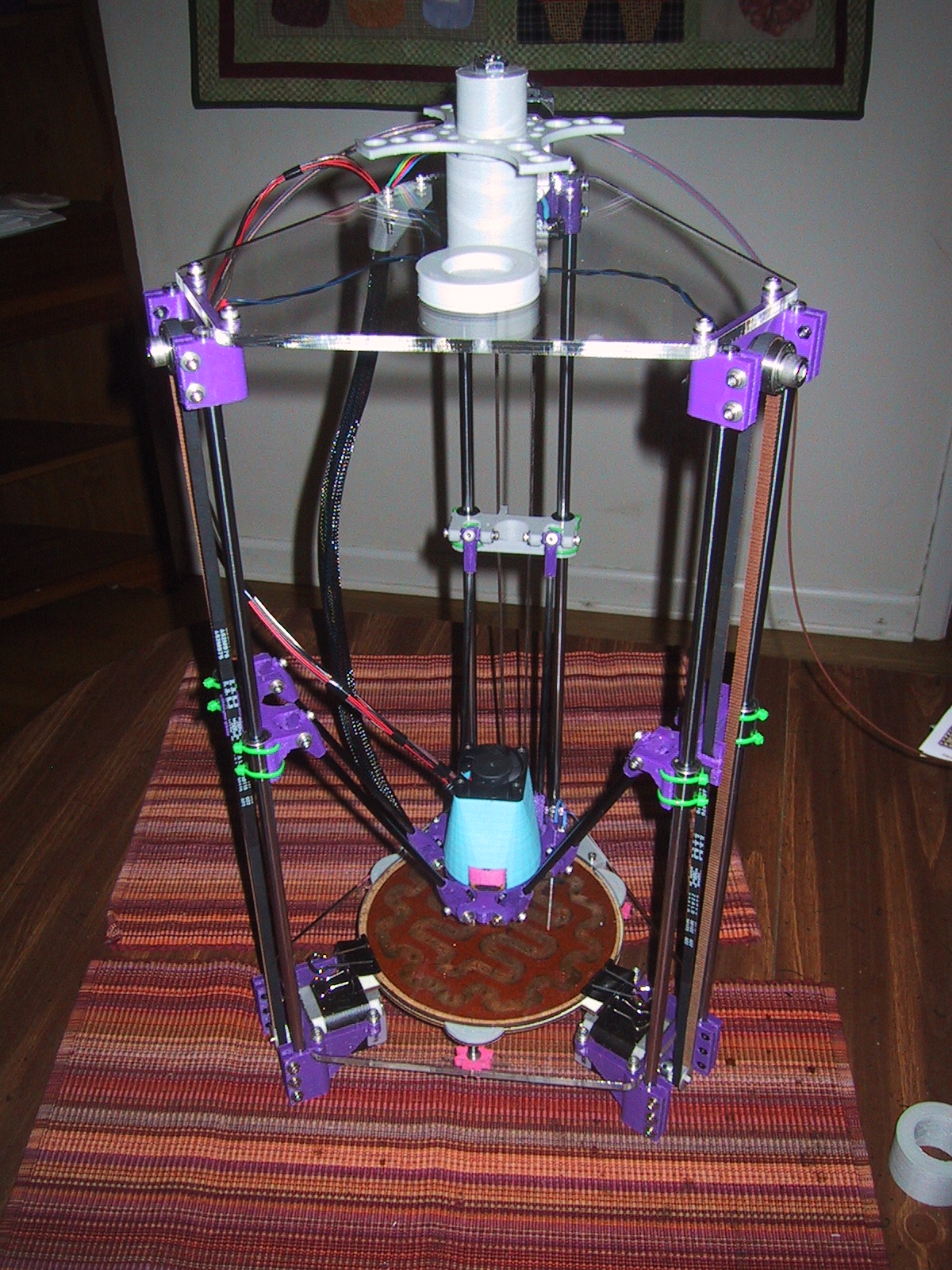
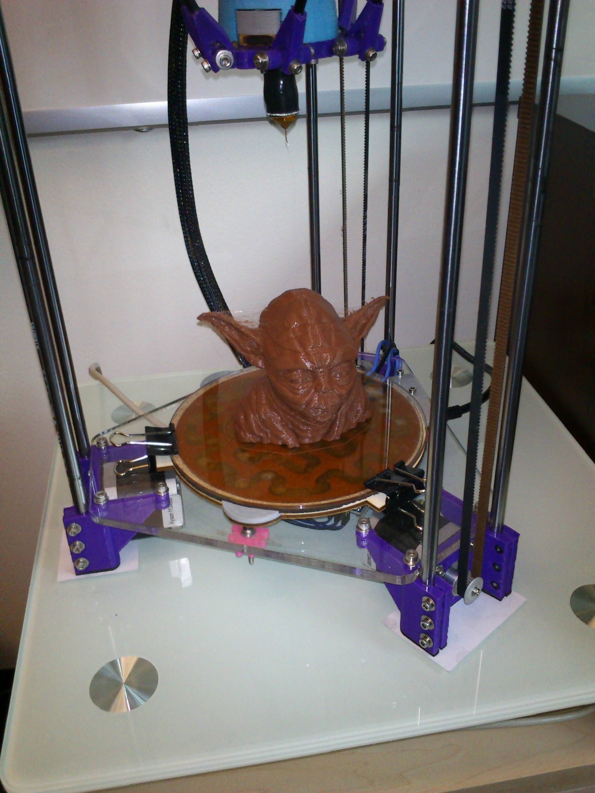
I have been printing Yoda busts on my Rostock Mini.

The first (small) sized one printed very well, but I had some problems when I tried scaling up to 160% size.
If you look closely, it has a small discontinuity just above the eyes. (It looks like the top of his head was sliced off and put back on slightly “off”.)
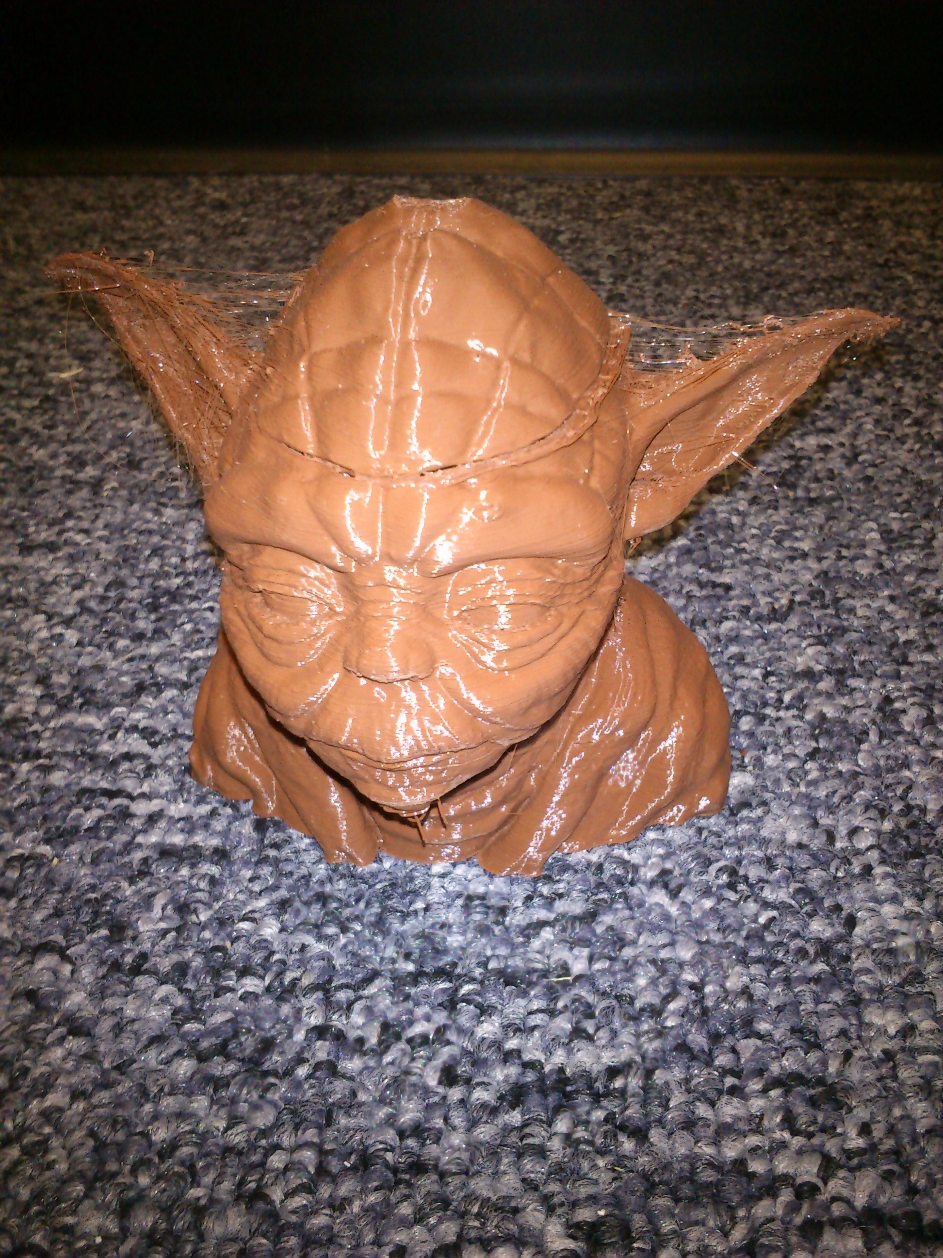
It looks like one of my axis lost a step, so I ran through various diagnostics (more airflow over the stepper drivers, higher current to the steppers, upgrading my slicing software, etc) and eventually the problem got worse:

Then I heard some squeaking from my 3D printer and started to move things around manually to isolate it and I realized that my straight rods and linear bearings were dry. The final solution was to oil my straight rod and liner bearings, although I can’t confirm that the upgrade to Slic3r didn’t also help things out. All in all, it only took four tries to get things right:
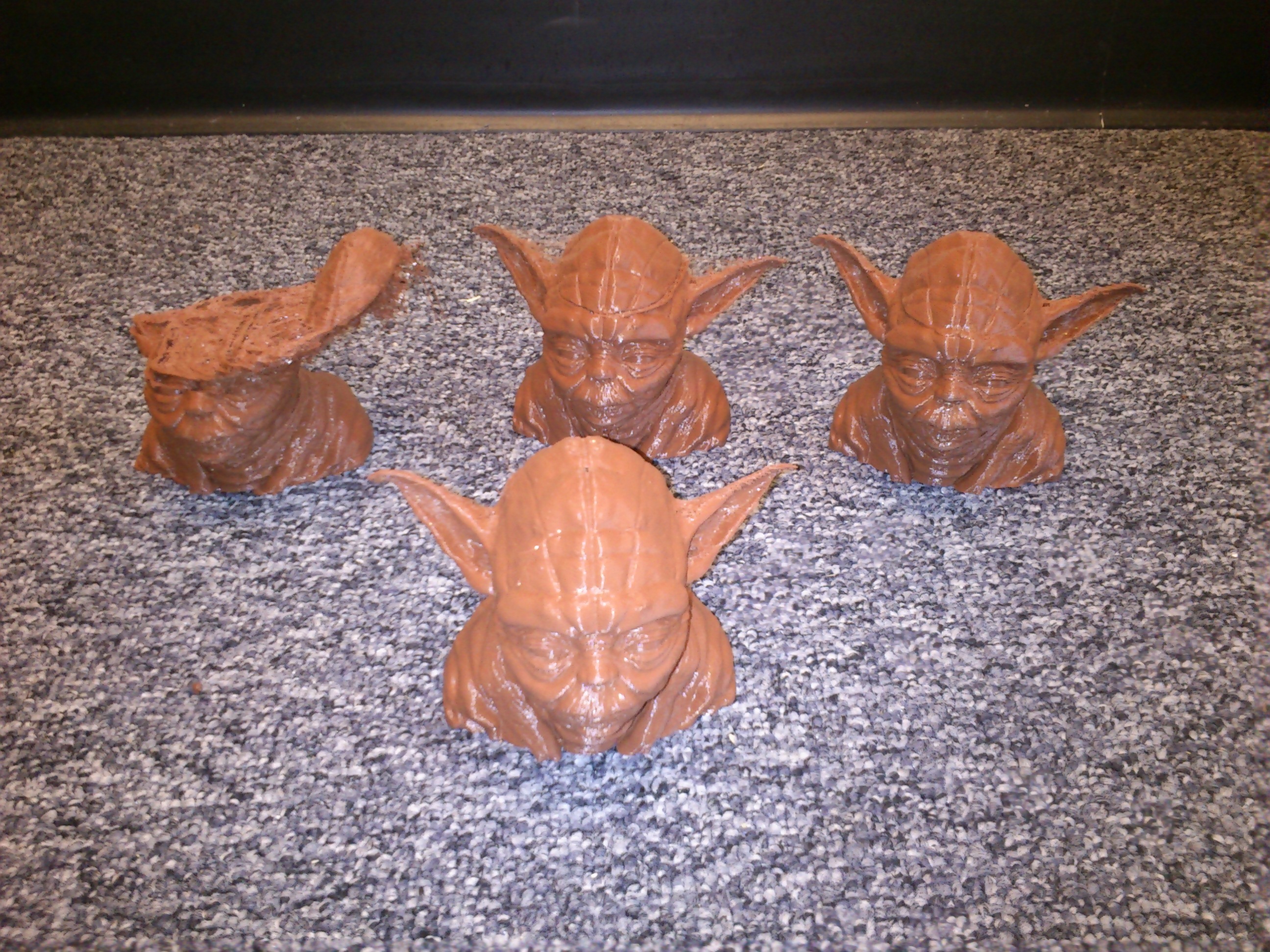
So now I have a large yoda head to float on my desktop levitation box: