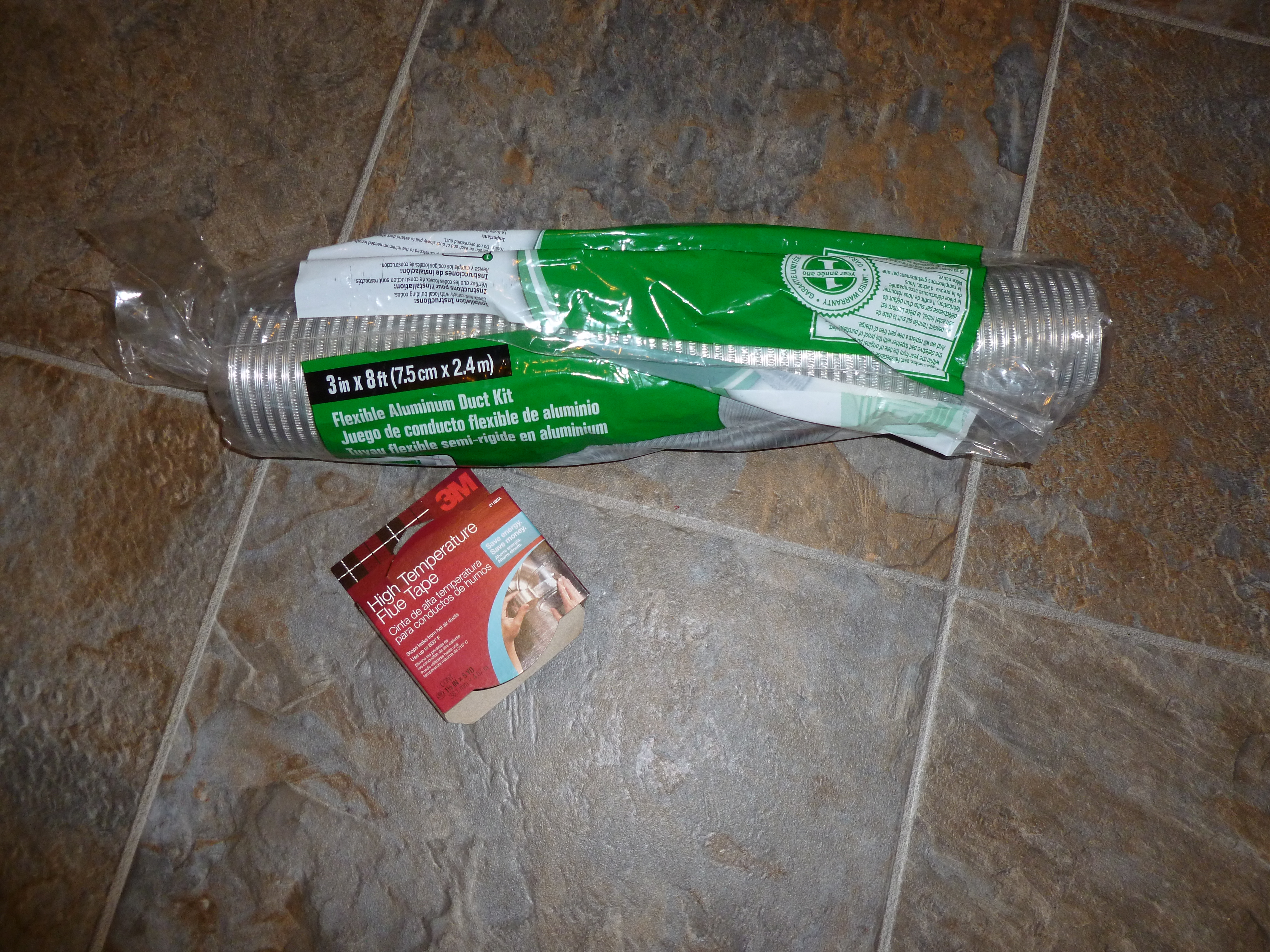
Since my first toroid was out of tune, I decided to actually follow directions this time and use an 8″ inner tube (2″ diameter) for my Toroid. I bought an 8″ inner tube and 50 yards of Aluminum Duct tape so I wouldn’t run out.
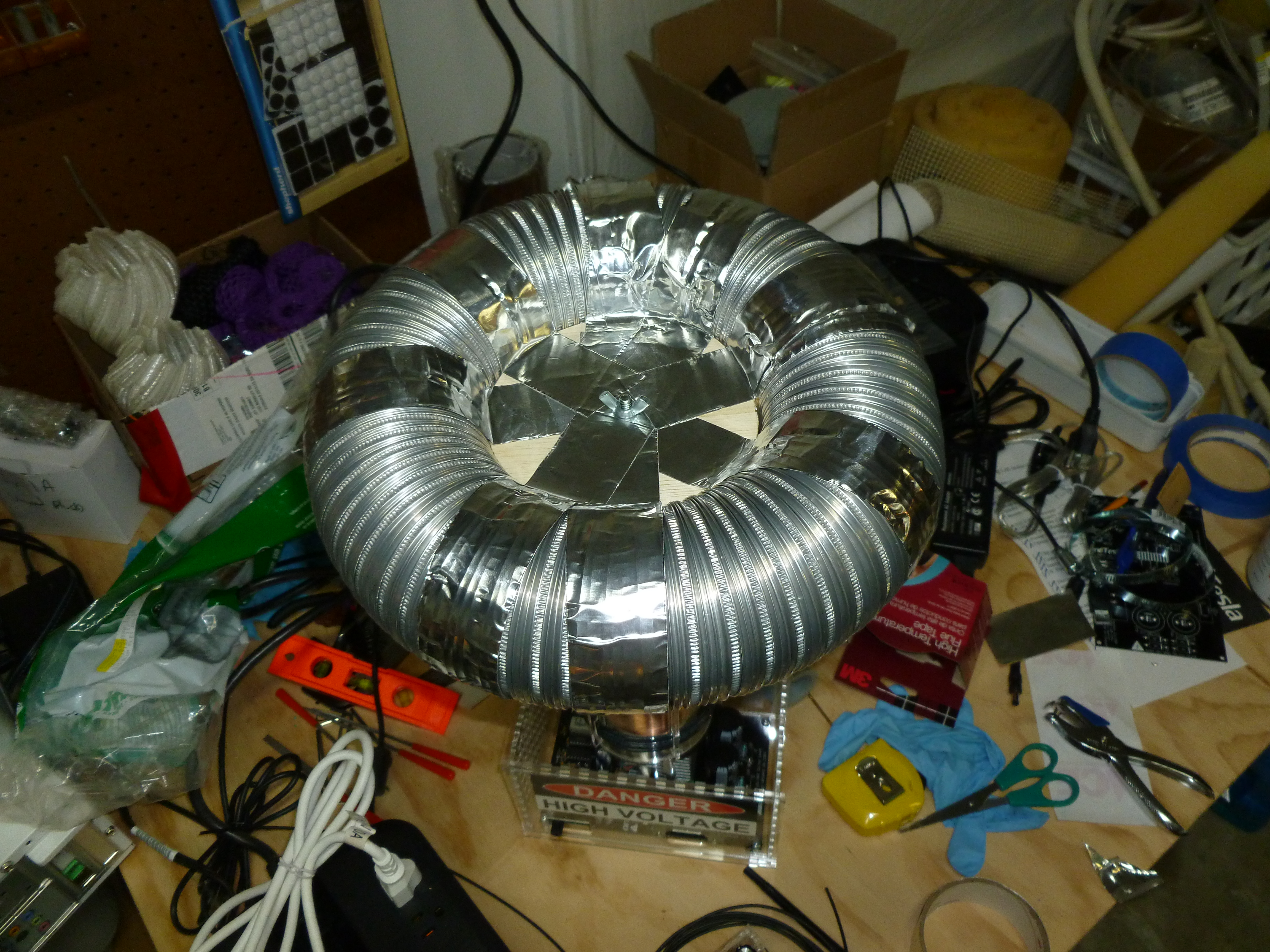
Then I went off-label and added a 4″ Big Daddio anodized aluminum personal pie pan which I’m going to try as a mounting system.

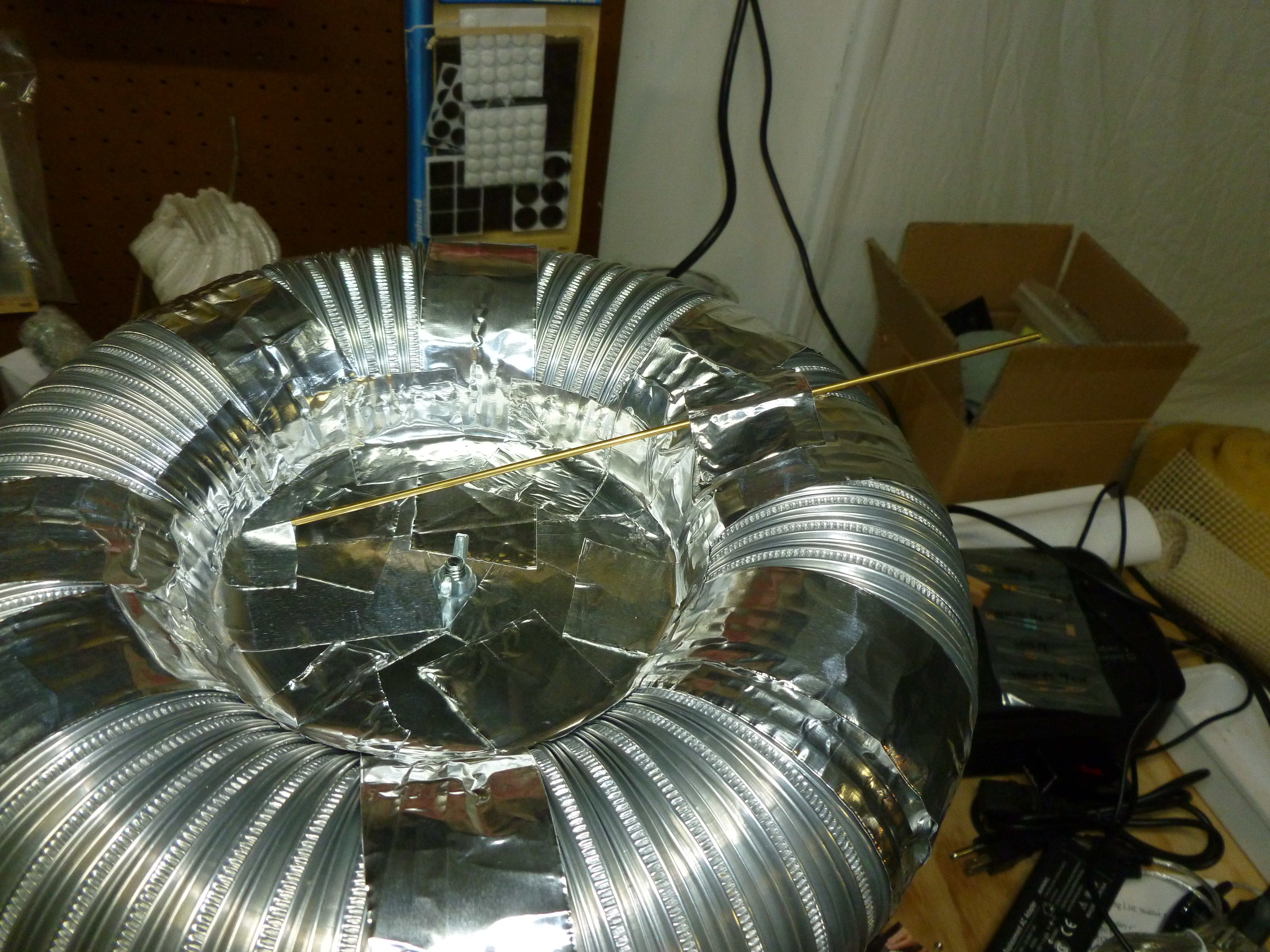
After drilling a hole in the base of the personal pie pan, I wrapped it and the inner tube with aluminum tape.
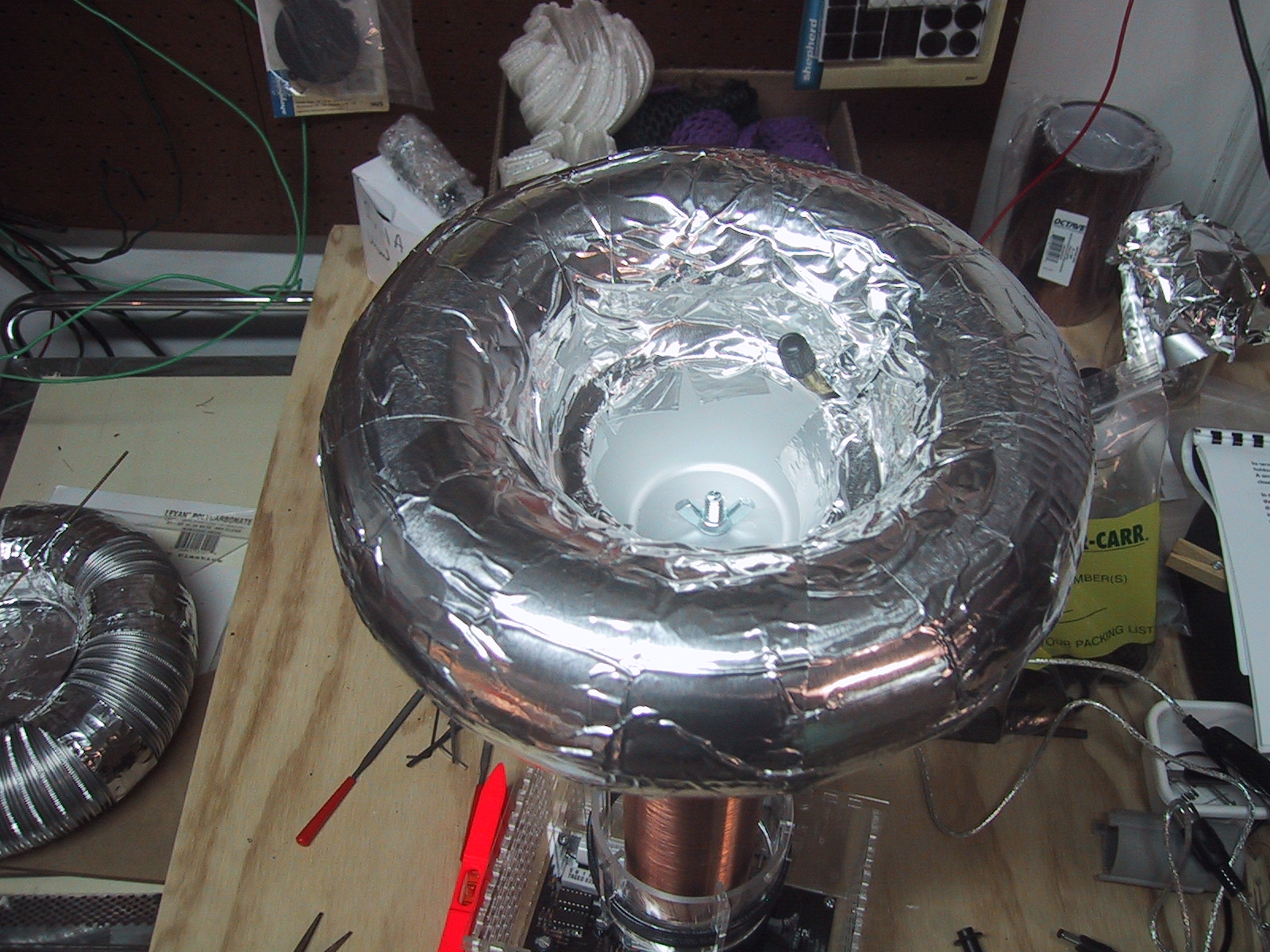
After this picture was taken I had to extend the aluminum tape down to cover the hole in the pie pan, as the anodized aluminum pie pan was apparently not conducting. After I did that I got less than 300 ohms resistance measurement from the outside of the toroid to ground.
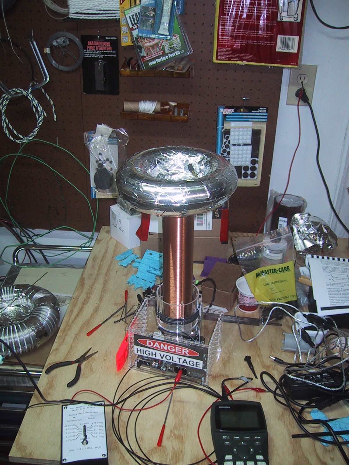
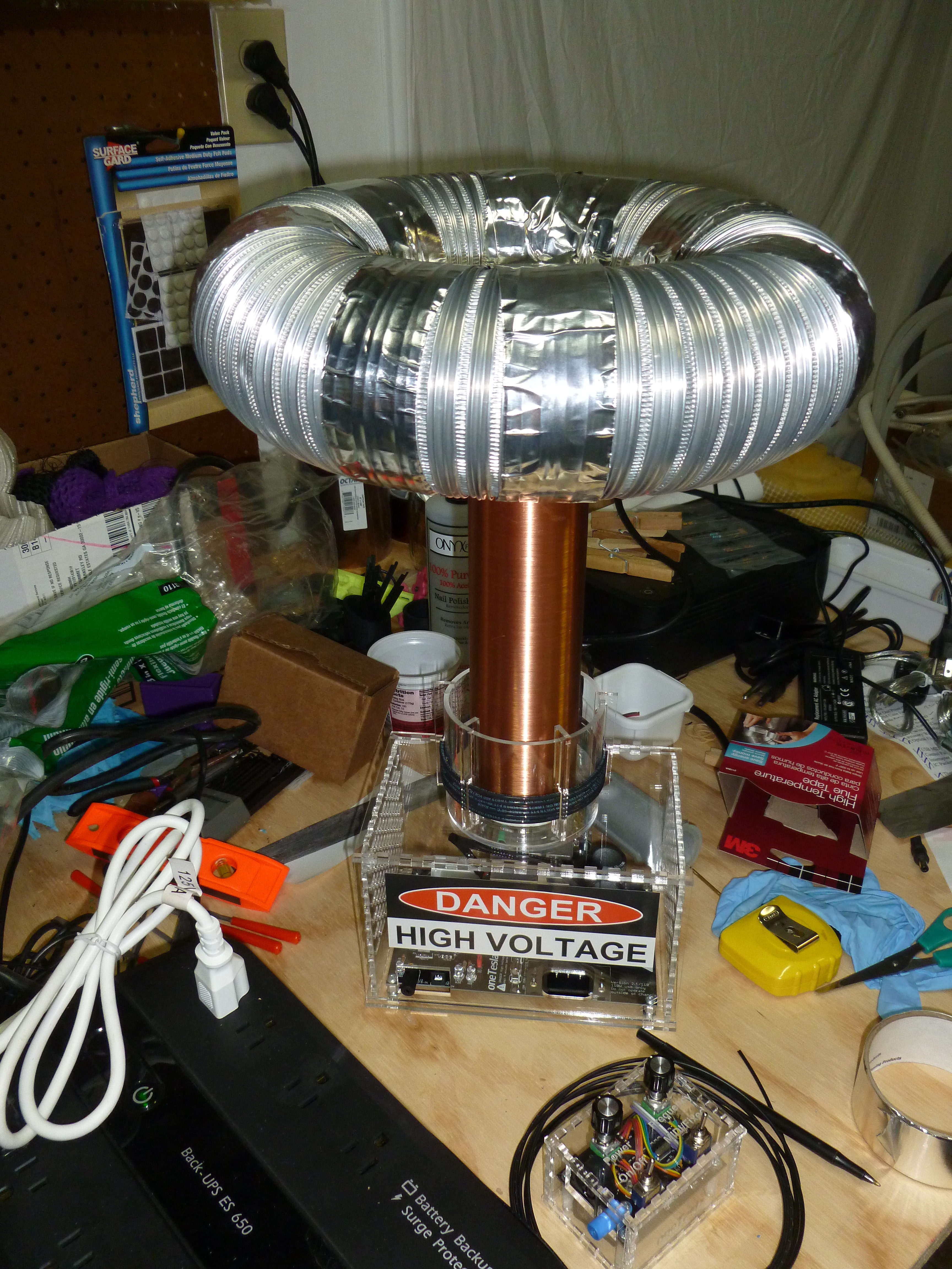
The size of this toroid is much closer to spec, although the Big Daddio pie pan holds it about 1″ higher than a straight piece of cardboard. Unfortunately, when I measured it’s resonance, I found a big signal at 340 kHz, (2.93 micro-seconds) which is even higher than my first toroid! Obviously I’m doing something wrong.