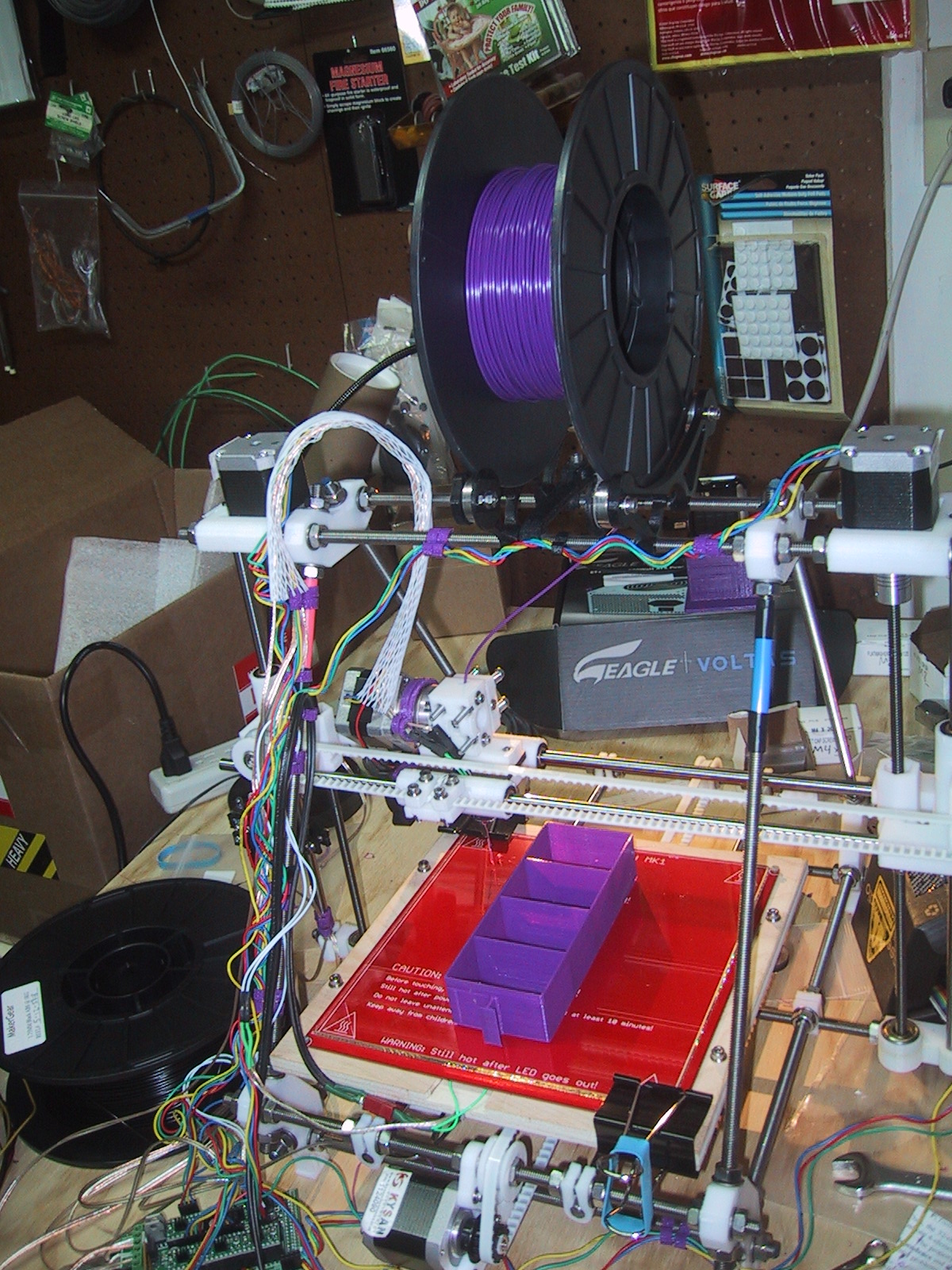
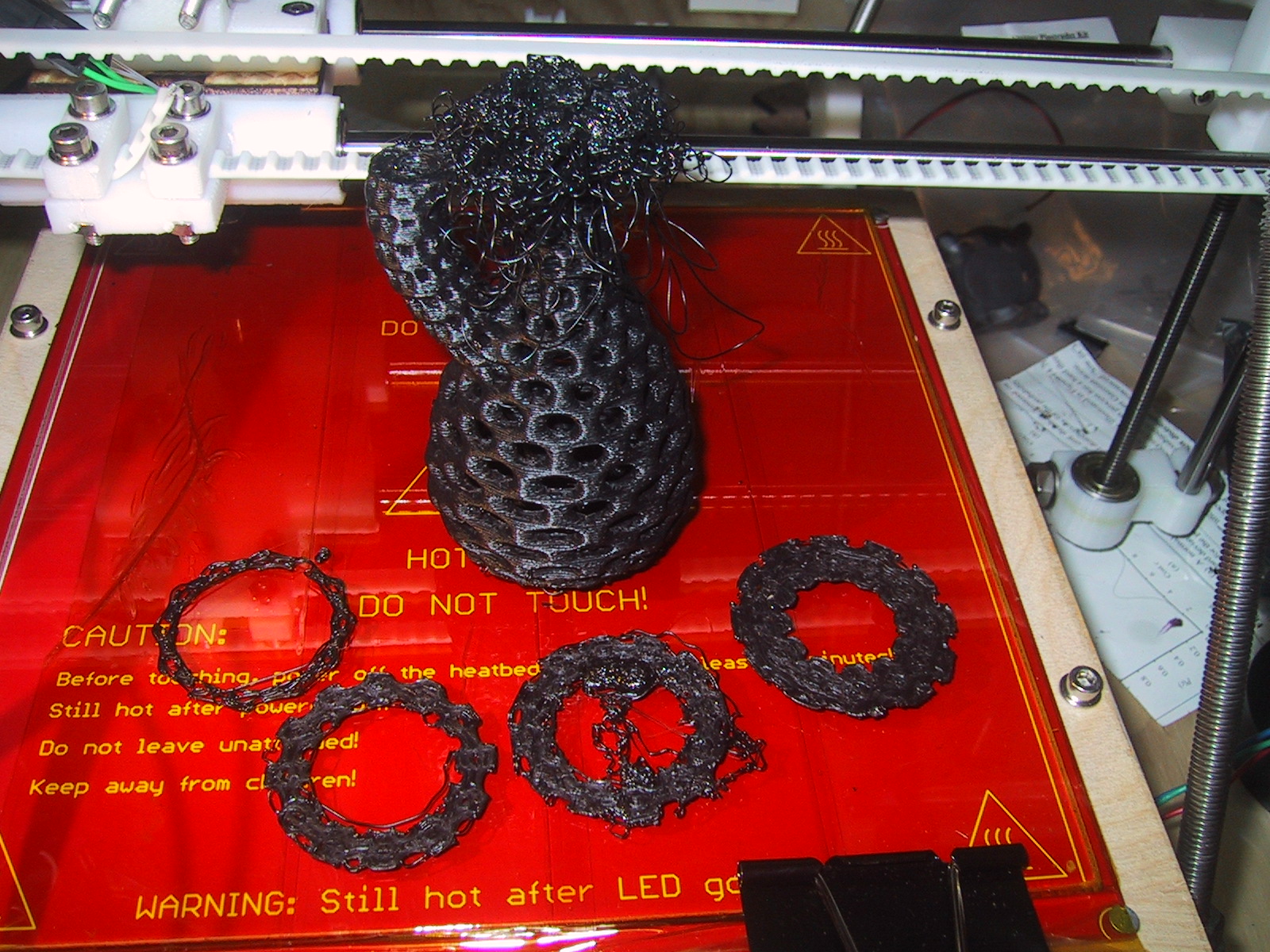
The biggest project that I am printing on my Prussa Mendel is all of the parts for a Rostock-mini which is a small footprint delta platform. Instead of having 3 different x/y/z axis, it has three identical towers that raise and lower carriages that are attached to the extruder platform by rods.
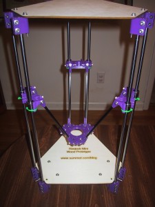
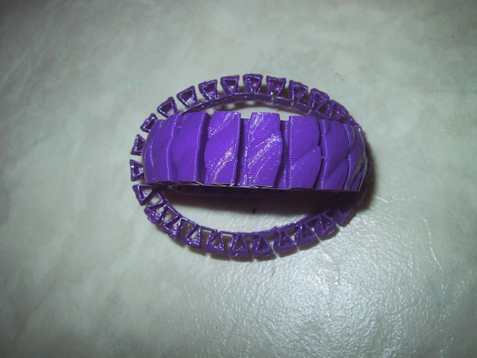
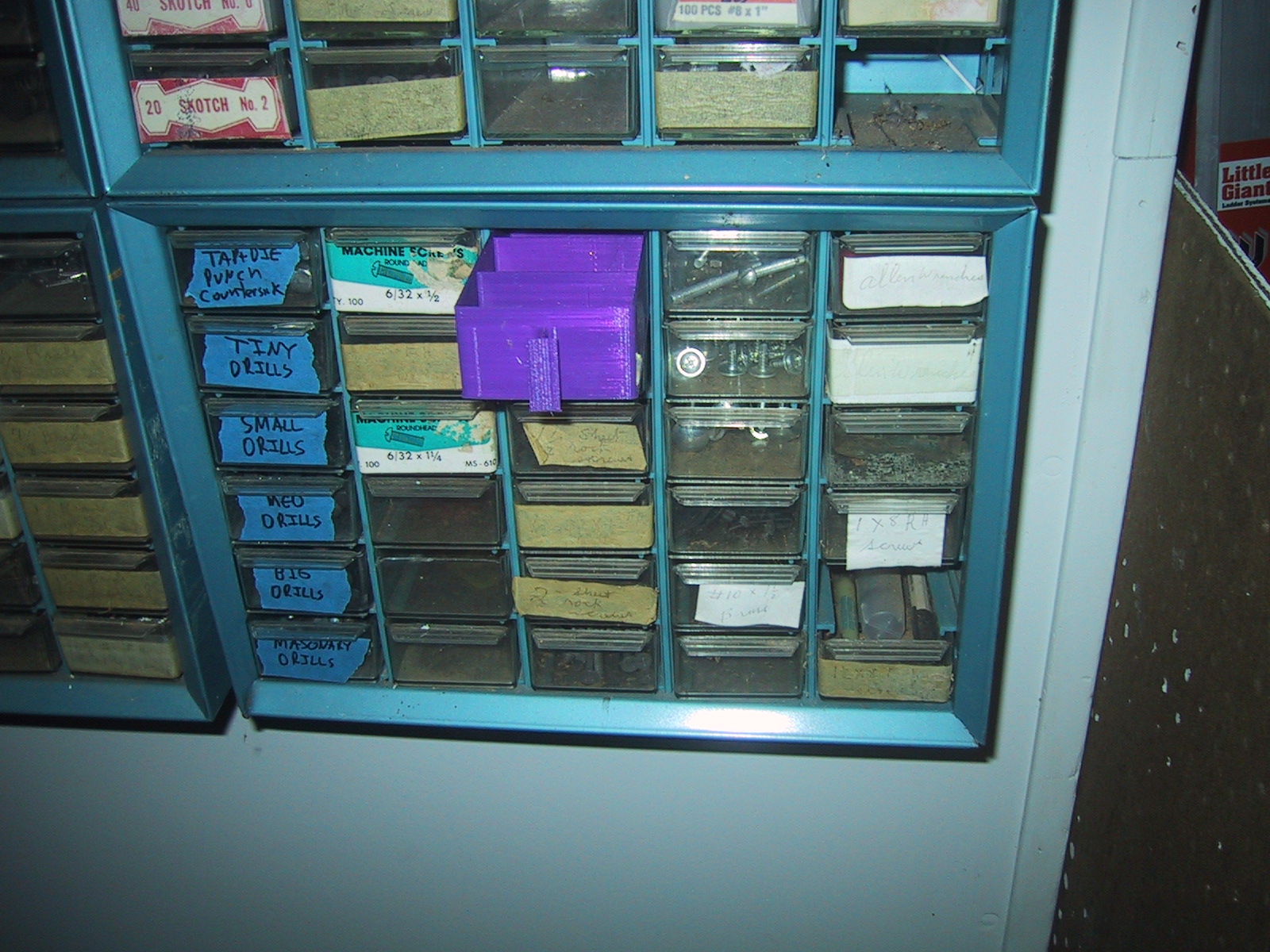
I choose to build this (2nd!) 3D printer for several reasons. First, I wanted a backup printer in case I broke something on my main printer. Second, the vertical design of the delta robots makes having a tall print volume very easy, and while the Rostock-mini will only be able to print in a 6×6 area, it can go up to 8 inches tall. My Prussa Mendel can do up to 8×8 inches, but is limited to objects of around 4 inches high. The only object so far where I have needed the full 8×8 build volume was the small organizer drawer which is longer than 6 inches, but I have several objects I want to print that are taller than 4 inches. Third, I really like the visual aesthetic of the delta mechanism, and wanted to have both types of printers. Finally, I wanted the experience of building the whole thing from scratch, sourcing all of the parts myself.
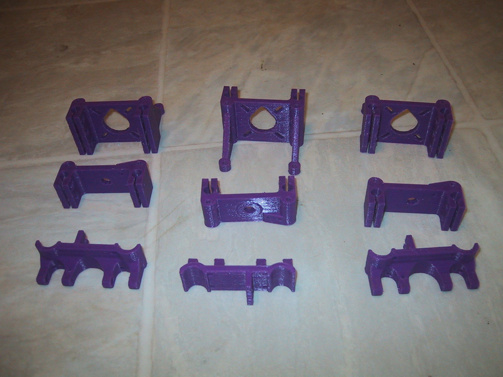
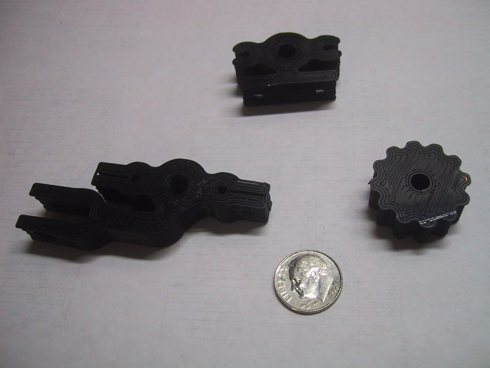
Brian Evans has done a very good job with the design on this printer, but the tolerances are very tight, so I needed to use a bit of trail and error when fitting everything together.
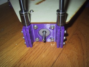
The motor & idler end use M3x12 screws to tighten the plastic around the vertical upright 8mm linear rods. When tight, the end of the screws don’t quite come all the way through the nut. I found it impossible to thread the screw into the nut until the plastic clamp was tight. I used a combination of M3x16 screws through the holes I wasn’t working on and a pair of plumbers (water-pump) pliers to get the plastic clamps close enough together so that I could thread the screw onto the nut. I recommend using a soldering iron to melt the hex nuts into the motor/idler ends to get an extra mm to make this easier. (However, watch out for my warning about threading into a melted on nut below…)
The major issues I had when building the rostock-mini frame arose mostly from the universal joints in the carriages and platform. The instructions say to melt the M3 hex nuts into the carriage and platform until they are flush. They also say to drill out the holes with a 3/32 or #40 drill. I found that when using a 3/32 drill the M3 screws would self tap threads into the plastic, so if the nut was just slightly off center, tilted, or not at exactly the right level, it was terribly easy to cross-thread the screw into the nut and bind them together, inside your plastic part. I had to use a haxsaw on three stainless steel screws until I got smart and knocked all my nuts out. I would thread/tap the M3 screws into the plastic until they were just to the hex nut indentation, and THEN put the hex nut onto the screw and get them threaded in place. I don’t have a ball end hex screwdriver that lets you drive a socket cap screw from an angle. Because the space between the inner universal joint holders on the carriages and platform was too small for my allen wrench (hex key), I ended up driving these screws by gripping their head with a pair of pliers (about 5 degrees at a time), which is REALLY annoying if you forget to put a fender washer on.

I suspect that you don’t need the M3 screws to self thread into the arms on either side of the u-joint, as the bolt/washer should hold them without plastic threads. I don’t know if you need the inside of the u-joint to be as tight as it is or not. If I were to build a 2nd one, I think I might drill out all holes not actually in the u-joints just slightly larger so that the M3 screws would clear without self taping threads. This would make assembly MUCH easier, and hopefully not introduce too much slop into the u-joints
I didn’t have any PTFE grease and couldn’t find any at the local hardware store, so I used spray on Tri-Flow which “contains PTFE” (I don’t know how much) but it appears to have made the u-joints move smoothly enough. I assembled the platform/rods/carriages before applying the lubricant (grease has the advantage that you can direct it exactly where you want it) and the entire mechanism was very tight before I sprayed all the joints with the lubricant. After spraying the joints everything worked much better.