Yes, I finally have all sixty tubes mounted and working. I still need to swap out two or three of the under-performing motors, and calibrate all motors, and do a lot of cosmetic finishing work (cover pieces for the top and bottom), and some software tweaks….but it’s finished enough to actually work!
Category Archives: Projects
22 of 60 tubes running – First scaling up problem rears it’s ugly head.
Here is a video of 22 tubes running with water:
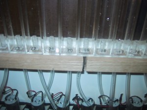
Now for the bad news….22 tubes actually measure 22 1/8″ wide. (apparently each tube is actually 0.00568 inches larger than 1″) This means my entire display would be 3/8″ too narrow, which just won’t work with the tolerances I have designed into my tube holder. That is why I only have 22 tubes in this video….the 23rd tube was just far enough off to not fit into it’s proper hole.
I fixed it by cutting the tube holder into 3 pieces and mounting them with a 1/4″ gaps between them.
I also had to space the end pieces of aluminum farther out, which meant I had to drill 4 new holes to mount the side brackets to the bottom board 1/2″ farther apart. Luckily the T-Sloted aluminum mounting system allowed me to easily move my L-Brackets up slightly to hit the new holes.
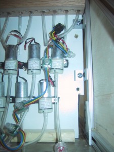
Unfortunately, I mounted the Shift MOSFET circuit boards on TOP of the screw heads holding the tube support board, so I had to take them all off to re-position the tube support board. Annoying, but not the end of the world.
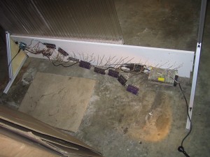
So, after a bit of additional work, I now have all 60 tubes working.
Electro-Mechanical systems complete
All sixty RGB LED’s and air pumps working under computational control. Next up, physical assembly.
Bubble Display update: 24 motors connected
Here is a video of the bubble display base with 24 (of 60 total) motors connected running a test pattern. Next up….lots more soldering. I’m very glad I was able to find strings of 20 RGB leds already connected!
First Light!
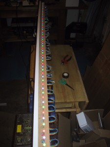
I have mounted and wired all sixty RGB LED’s under the tube support shelf. These RGB LED’s are in serial strings of 20 each, and I was able to connect them end-to-end, making the wiring much easier than the air pump motors! Each liquid filled tube in the bubble display will sit above one of the LED’s.
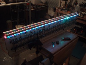
These LED’s are individually addressable by the Arduino that controls the entire system. In the video below I have them simply doing a simple color progression for testing.
Motors Done!
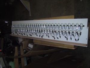
I have all sixty of the air pumps soldered to connectors and mounted on vibration dampening foam. Thirty are in a line on top 1 and 7/8″ apart, and the other thirty motors are mounted offset just below them. The connectors will allow easy motor replacement if one should fail. (A screw, an electrical connector, and a 1/4″ tube will need to be moved over to the new air pump.)
My super high tech vibration dampening material is simply 3/8″ strips cut from donated black rubber mouse pads.
Frame and Tube support
Here is the final frame (without covers except for the triangular end pieces):
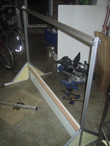
I cut the extruded aluminum t-channel pieces to the correct size and assembled them with the MDF tube support and plywood end panels (not yet stained/finished).
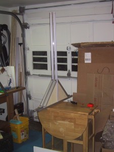
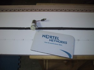
Here is a picture of one side panel, plus a “one tube, one inch wide” bubble display that I mocked up before getting the tube support finished:
The two end panels are connected at the bottom by the tube support, which is just a MDF shelf on it’s side cut to the correct length. This piece of MDF rests on the ground along its entire length and serves as the support for the tube holder. I used a carpenters square and a level to make sure the tube support (and end panels) were square and correctly upright while attaching it. I would attach one bolt, and then square everything up before attaching the other bolt.
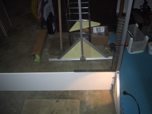
The tube support is screwed to the tube holder MDF using 32 wood screws. I might have been able to get away with 16…but I know 32 will hold!
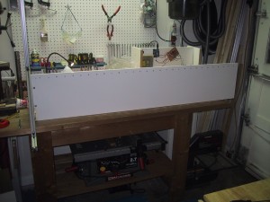
As pictured here, the frame without electronics, tubes, motors or front/back covers weights in at 30.2 pounds.
Next up: Drilling 60 holes to mount the motors, and 30 or 60 holes for the motor power wires (I may combine the wires from two motors into the same hole, I haven’t decided yet) … and soldering connectors onto 60 motors (Which goes at around 20 motors per hour….).
Tube Holder
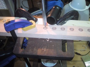
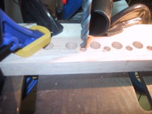
The Tube Holder is a piece of hardwood that sits directly beneath the tubes (holding their weight) and has holes for both the air injection tubing and the RGB LED lights for each tube. I made it out of hardwood because I had to drill 120 holes in it, and because it would be screwed to the tube support upright which is MDF.
The tolerances for the holes are relatively small, so I was careful in measuring, marking, and drilling.
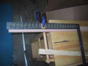
Every inch a 1/2″ spade bit was used to drill a hole for the air tube, and then between them a 5/16″ bit was used for the RGB LED light.
Scaling wide to sixty tubes!
How do you make sixty bubble display tubes?
One. By. One. Well, actually, you do sixty duplicates of each individual step. The steps are:
Continue reading
Bubble Display Frame – Test Assembly
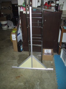
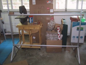
I am using T-Slot aluminum extrusions for the frame of the full sized bubble display. After I made the CAD plan, the decision was made to shorten the display to 36″ tall tubes (The width will be 60 tubes / inches). This allowed me to shorten up the support legs as the center of gravity of the frame will be much lower. I haven’t actually cut any of the aluminum stock to size yet, so the photos below show pieces of aluminum extending out the back and top, and it is 72″ wide instead of 62″ wide. You can see a single tube mounted with a rubber band on the far left. The piece of cardboard on top of it is taking the place of a metal mesh that will eventually mount over the top of the tubes, running the entire width. (The bottom cross support is simply to hold the frame up, and will probably not be visible in the final assembly either.) The triangular prism at the bottom of the frame will be covered with panels of plastic or wood, and contain the electronics, LED’s and pumps.
