Dual hose portable AC window adapter & Whynter ARC-14SH review

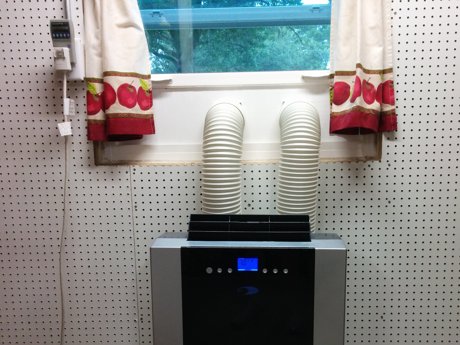
I found a good deal on a used Whynter ARC-14SH dual hose portable air conditioner and have installed it in the storage room off my garage. If I leave the door open it can help cool the rest of the garage, or if I close the door, it can condition the air in just the storage room quite easily.

I wanted something a little more permanent and secure than the included plastic window adapter kit, so I cut a piece of 1/2″ plywood to fit inside some convenient pre-existing slots in my single hung window, attached the hose end-plates to it and painted it with exterior paint.   The board fits into the window just inside the existing screen, so I don’t have to worry about bugs getting into the inside of my AC unit. Here is a video montage of building the window adapter.


I was considering a window mount unit, but this portable unit gives me the flexibility to mount it inside the garage later (venting out the ceiling to the Fascia) or wheel it into the house to use to cool a single room if the main AC goes out.   Obviously, having outside and hot exhaust air cycle through two hoses inside the conditioned space is slightly less efficient than a window unit, but it’s much better than a single hose portable AC unit, which will cause outside air to slip into your building as it exhausts it’s waste heated air. It also presents a cleaner look on the outside of the window. (It does take up more floor space inside the room however….)

The EER rating for this unit is 11.2 according to the Home Depot website.   A comparably priced 14,000 BTU Energy Star window air conditioner from GE has an EER rating of 11.8, so from an efficiency standpoint the portable dual hose model isn’t terrible.

The unit draws a maximum of 10.5 amps, and appears to hover around 1050 watts when the compressor is running and 45-65 watts to just run the fan, depending upon what speed the fan is set to. I usually leave the fan on low if only cooling the storage room, and turn it to high when cooling the rest of the garage. The compressor is at least as noisy as the fan in “high” mode, so don’t expect “low” mode to be quiet AND condition the air at the same time, although you can run the unit in “fan only” mode if you just want to circulate air.   The unit is a bit noisy (56 dBA). This is not bad for a workshop, but could be an issue in a bedroom or media room. (In comparison, a nice mini-split ductless AC unit usually runs closer to 34 dbA.)

In AC mode it uses the collected water to evaporatively cool the hot side, and exhausts the humidity with the rejected heat, so in my experiance doesn’t need to be otherwise drained. (This hot moist exhaust air is another good reason to paint the entire adapter board with exterior paint.)

If you run it in “dehumidifier” mode (where it attempts to remove water vapor without putting too much energy into cooling) you are supposed to vet the exhaust air back into your conditioned space to prevent “cooling” from happening. (Living in Florida, this probably isn’t an issue for me….). But, you also need to remove the collected water. Because this is primarily an AC unit, it doesn’t have a large water reservoir, so to use it effectively as a dehumidifier, you will NEED to rig up a permanent drain hose of some type. And, because the drain is located about 2″ above the floor, you may need a pump system unless have have a conveniently located floor drain nearby.   I haven’t tested the heating mode, but according to the manual it has one that will work with outside air down to 45 °F. It also has some timer modes to turn on or off after a set number of hours which I also haven’t used yet.

Practicalities of On-board solar charging for small EV’s

I’ve been running the numbers on building a small 1-2 person “motorcycle” (3 wheeled) electric vehicle, and was considering adding two 330 watt solar panels to act as the hood and roof/sunshade, which would provide shade for the driver and charging from the sun.

The drive motor I was looking at runs at 96 volts and 95 amps to drive a 325 lb vehicle (with 170lb rider) at 60+ mph. Twelve Nissan leaf modules would provide 96-100 volts at 60 ah for a total storage capacity of 5.7 kWh (giving around a 45 mile range at 60mph, probably close to a 60 mile range at 35mph, an efficiency of   between 83-111 Wh/mile).   This battery pack would weigh 100 lbs, plus BMS/mounting hardware and wiring.

Weight Considerations

Two 330 watt solar panels mounted on the roof/hood would also weigh 100 lbs.This could conceivably be 30% or more of your vehicles weight budget.

With around 6 hours of good solar exposure a day, they would probably provide around 600 watts per hour, or 3.6 kWh of charge (a gain in driving range of between 32-44 per day). They could fully charge my hypothetical 5.7 kWh battery pack in two days.

More batteries?

The alternate way to spend this weight budget is to double the battery pack size. This would give a 11.5 kWh battery pack, giving 90-120 mile range from a single charge. A side benefit is that the extra 100lb of weight could be placed low to the ground, instead of up high on the roof of the vehicle, greatly improving performance on corners.   (Also, the aerodynamic effects upon handling and range of adding a horizontal sail to the top of your vehicle must be considered….)

In my opinion, if you are regularly returning to a home charger, it is more practical to use extra weight allowance for batteries, as opposed to solar panels. Solar panels make the most sense when the vehicle is designed for non-round-trip applications, such as with an RV/Camper or road trip vehicle.

Bigger/Faster charger?

For an “in-town” vehicle, where J1772 (level 2) chargers are readily available, adding a high speed on-board charger (6.6kWh) would allow you to refill a small battery pack in under an hour, and would add less weight than commercial solar panels or extra batteries.   Having an extra 15 lbs of charger instead of an extra 100 lbs of solar panels or batteries would lower your rolling resistance and increase your range and acceleration.

Specialized solar panels

Alternate solar panels (smaller RV style, or thin film flexible solar panels) would weigh slightly less, but the weight savings is not as impressive as you may think. A 330 watt “house style” panel weights 50 lbs, or 0.15 lb per watt. A 100 watt RV panel weights 15 lbs, or the same 0.15 lb per watt. A 72 watt PowerOak flexible panel weights 6.2 lbs, or 0.086 lbs per watt. This is a weight savings of almost 50%, but unfortunately they are much less efficient, so would need more surface area, something in short supply on a motorcycle class EV, plus they cost much more on a per-watt basis.

Custom Alternatives

If you wanted to take the time to fabricate your own solar panels out of individual cells as part of a fiberglass layup, you could conceivably make them weigh less and fit the contour of your vehicle better, possibly integrating them into your vehicles body.   But if they are integrated into the skin of your vehicle you have to worry about solar heat gain. I think it would be better to have them mounted as a “shade” or “2nd skin” just above your vehicles main body with airflow channels between the two.

Cost Considerations

100 lb of 330 watt solar panels (two) cost around $500, while a 100 lb Li-Ion battery pack would cost about $1200-1500 (unless salvaged from a surplus battery pack). So the solar panels could cost less than a larger battery, but would require more work to integrate into the vehicle. A 1.5 to 2kWh charger would be fully adequate for a vehicle with a 5.7 kWh battery pack. You could even have only 110V charging (1kWh) and save the expense and complication of a J1772 inlet, while still being able to recharge a fully used battery pack in six hours. A minimal charger like the ELCON PFC1500 would cost $575.   An Elcon PFC 5000 ( TCCH-84-50 ) could charge at 5 kW, giving a small EV an almost “QuickCharge” charging speeds for around $2000 with J1772 inlet/adapter.

Modular Vehicle

One option would be to mount several solar panels on a trailer (possibly with a 2nd battery pack, and even extra motors) to be used only on longer “road-trips”. It is possible that the trailer could have room to hold 4×8 sheet goods, and/or a sleeping compartment under the solar panels for road trips. If the solar panels could swing up, it could be used for transporting larger furniture or appliances. (Consideration would have to be given to adding a lower gear ratio to the tow vehicle, or including extra motors on the trailer itself for heavier loads.)

Curtis 1231c upgrade: Binning Gate Drive Resistors

I am upgrading the power board of my Curtis 1231c DC PWM motor controller. It uses 18 MOSFETs to switch the power, and each MOSFET had a 47 ohm resistor on it’s gate input. The point of such a high resistance was to slow down the switching of the MOSFET’s so that they would all share the current somewhat equally and no single MOSFET would turn completely on before all of the others had a chance to start shouldering the load.

Continue reading

Curtis 1231c Power Board desoldering

I desoldered all of the main power components (diodes, MOSFETS, capacitors) from the power board of my failed Curtis 1231c PWM DC motor controller. The plan is to upgrade all of the components to give it higher capacity; while producing less heat. Of course, to replace them, I had to remove the old ones, which took around 6 hours of work with two different soldering irons and a solder sucker.

My advice:
-Heat component legs (diodes/MOSFETS) from the top of the board (side with the component) while you solder-suck from the bottom. Get one leg completely free first, then work on the other. After you suck almost all the solder out, you may still need to re-heat the leg and push it away from the PCB with a small screwdriver so it doesn’t stick to the inside of the hole.
-For the capacitors, don’t be afraid to add a little solder to the smaller leg, and then use a 100 Watt super wide tip soldering iron to heat both legs up at the same time, and pull the capacitor straight out. Suck the solder from each hole individually later once all the components are gone.
-I heartily recommend the Engineers SS-02 Solder Sucker, the silicon tube it uses is great! I did get solder stuck inside the metal tip a few times, but nothing a 5/64th drill couldn’t fix right up.
Continue reading

Curtis 1231c diodes: Diotec DR7506FR vs TSR2402R

I am looking to replace the MOSFETS, diodes, and capacitors in my Curtis 1231c with upgraded components. I unsoldered one of the existing TSR2402R (7103 K) diodes from the power board and tested it with my Fluke meter and bench power supply.

Here are my results:
Power Supply providing 3.2A, forward voltage drop: 0.776 volts
Power Supply providing 2.0A, forward voltage drop: 0.737 volts
Power Supply providing 1.0A, forward voltage drop: 0.697 volts
Fluke Diode Setting: 0.351 vdc

Average time for the button temperature to raise from 25 °C to 50 °C with a 3.2A current: 45 seconds

The replacement parts I purchased were from DIOTEC, specifically their DR7506FR model (the R at the end means “Reverse Polarity”, making them an exact drop in replacement in form factor and polarity). They were marked: “DT110   DR7506FR” plus a diode schematic. Here are my results for the upgraded component:

Power Supply providing 3.2A, forward voltage drop: 0.754 volts
Power Supply providing 2.0A, forward voltage drop: 0.700 volts
Power Supply providing 1.0A, forward voltage drop: 0.646 volts
Fluke Diode Setting: 0.399 vdc

Average time for the button temperature to raise from 25 °C to 50°C with a 3.2A current: 47.5 seconds

Of course, the original diode I’m measuring had been in use for many years (I estimate ~750 hours of driving time given the 22K miles) and was heated up as part of the soldering and unsoldering process, while the DR7506FR I tested was brand new straight from the manufacturer. After I unsolder a few more diodes I’ll check them to make sure their readings are similar. (I’ll probably also test a few other DR7506FR diodes from the bag as well.)

Of all the measurements, the temperature rise time measurement was the least scientific, as I was using an inexpensive non-contact IR thermometer and attempting to point it at a small button in each diode, waving it back and forth to find the hottest temperature. I took 4 measurements on each diode (alternating to let the other one cool down) and averaged them together. In general, the readings from the DR7506FR were longer than from the original TSR2402R with one exception. If I throw out that pair of readings, the averages would be 46 seconds vs 50 seconds. Given that the measured forward voltage drop for the DR7506FR was lower for any real amperage readings, it dissipating less power and taking longer to rise to 50 °C appears to be reasonable.

Curtis 1231c Replacement Power board components

My Curtis 1231C motor controller blew up some MOSFETs and died. I replaced it with a used unit to get my truck back on the road, but now I’m interested in repairing the one that died so that I’ll have a spare.

I might be able to replace the components that died with exact replacement parts (but the IXTH50N20 MOSFETs are hard to find nowadays, and the diodes are basically unobtainable) to get it working, but since I have it open and am doing all of this work, I am exploring alternative (new) components that will have higher ratings and possibly give my controller more capacity or at least more resistance to blowing up again.

Of course, if I replace one component (power switching MOSFET, freewheeling diode, or ripple controlling capacitors), I will probably need to upgrade the other two as well so that I don’t just move the weak link from the MOSFETS to the capacitors or diodes.

Continue reading

Curtis 1231C-8601 500A PWM DC Motor Controller teardown

After replacing the Curtis 1231C-8601 motor controller that had failed, I opened the case up to figure out what had failed.   The controller hardware is inside of an aluminum extrusion with both ends “potted” with some black semi-flexible material (hard silicon perhaps?) that could be cut using a razor knife and a lot of effort.


Inside, there is a Pi shaped piece of aluminum extrusion that acts as the heatsink for the MOSFETS and freewheeling diodes, as well as being electrically connected to the motor – terminal. It is held against a large thermally conductive, but electrically insulating pad, which separates it from the controller case, but allows heat to be dissipated. It is held in place with 8 screws that pass through insulating plastic brackets into the bottom of the case.

People online had told me that these screw holes were “potted”, but on my controller they were just filled with two rubber plugs.They also told me that you could not cut through the Curtis potting material with a razor knife. [This super hard potting material was also prone to cracking at the edges and letting moisture into the controller, so a flexible rubber like material is better anyways…]

Continue reading

Build a workbench from plywood and 2×4’s

img_20160816_160641img_20161111_113437

This is the workbench I build from twenty-two 2×4’s and three sheets of plywood. Because my current garage has tall ceilings, it has a lofted storage shelf. And it also has a shelf for tool and box storage below.

I used two sheets of 3/4″ builder grade plywood for the lower and upper storage shelves and a 1/2″ sheet of sanded ply for the main workbench. The dimensions were carefully chosen so that all of the excess can be used for reinforcing sheathing.

Continue reading