AT&T U-Verse upstream speed bump in June

I have an AT&T U-Verse “Internet Pro” DSL account. In the middle of June (near the 13th) my latency suddenly improved by 10ms.
latency

Then around the 19th of June (2014) my upstream bandwidth jumped from around 1 Mb/s to around 1.4 Mb/s:
upstream

AT&T doesn’t advertise or make any promises about their upstream bandwidth, but these are welcome changes (especially the 40% boost in upstream bandwidth). My downstream bandwidth stayed just above the advertised 3 Mb/s rate.
downstream

I don’t know if this was due to a piece of equipment near my home getting upgraded, or the result of a policy change to upgrade the “Internet Pro” account, but I’ll take it!
Anybody else see a similar boost? Or have a negative counter example?

Small Phone Review: Sony Ericsson Xperia Mini cell phone

I recently purchased a Sony Ericsson Xperia Mini ST15a Cellphone to see if I would like it enough to replace my HTC Aria / Liberty A6366. (I did a review of the aria here.)

Form Factor:
I specifically picked the Xperia Mini because it is a small phone. Small enough to fit in my backpack’s older style cell-phone pocket. Small enough to (easily) fit in my front pocket if I want to carry it around without my backpack. From an outline standpoint, it is actually smaller than the HTC Aria, (and weights a half oz less) but it is almost 50% thicker (only 16mm or 0.63 inches). I was slightly worried that it might be a bit too thick, but after using it for a few days I have decided that it’s fine. The extra thickness is nice to keep it from disappearing in my hand…it’s a VERY small form factor for a modern android smart-phone.

Buttons & Ports
The audio jack comes out the bottom of the phone, which means I have to put it in my backpack’s cell-phone pocket upside down when listening to music with headphones. The micro-USB port is also on the bottom, and covered by a small removable plastic tab that is “hinged” to the phone with a small piece of plastic that goes into a hole. I doubt that the plastic tab will last for more than a few months, as I plug in the phone to charge at least twice a day. The USB port has a “square” appearance, and does not look like a micro-USB on first glance. You have to look inside of it to determine which way is “up” (it’s “upside down”…), but a standard micro-USB cable does work with it. Not major issues, but I don’t see the point of having a removable cover for a port you are going to be using multiple times a day.

A volume up/down rocker is on the top right side, and the bottom right side has a dedicated camera button. You have to long-press the button to auto-start the camera application, I have never started it by accident, and it’s nice having a dedicated button to pull it up. The power button is on the top left.

The battery cover/back of the phone snaps on and off from the side and wraps around the back of the phone. You have to pull the battrey to change the SIM card, and the back cover has a small plastic tab that holds the MicroSD card in when the cover is on. (You need fingernails or tweezers to remove the microSD card, it does not have any push-spring-return mechanism.)

The phone’s speaker, LED flash, and camera lens are on the back.

Screen:
The screen is just slightly (0.2in) smaller than that of the Aria, and has the same resolution (320×480). Even at the full brightness setting it doesn’t appear to be as bright as the Aria’s screen, but I haven’t noticed it being too dim either. According to the Internet, the glass is “scratch resistant” but not “Corning Gorilla Glass”. I typically use a plastic screen protector on all of my phones (at least for the first year or so) and keep them out of pockets with keys, so the exact type of glass probably doesn’t matter. Percentage wise, a much larger portion of the front of the Xperia is screen.

Software/UI:
I purchased a phone that was not carrier branded, so the only pre-loaded apps it had came from Sony Ericsson. I was able to remove, disable, or hide all of the annoying pre-loaded offers and things I didn’t want, and almost immediately downloaded the Sony Phone Companion software for my PC to upgrade the phone to Android 4.0.4, so I can’t comment on the original Android 2.x OS that the phone originally shipped with.

Android 4.0 on the phone is as good as my CyanogenMod ROM on the Aria. My phone has full support for setting itself up as a wifi-hotspot for wireless tethering. (Perhaps carrier branded versions of the phone have that part of android disabled?) It also supports various VPN’s out of the box (noticeably lacking is OpenVPN, I had to set up a PPTP server at home, which was actually a lot easier than getting an OpenVPN server working). In short, the stock OS/ROM did everything I want from a phone, so I don’t anticipate having to root the phone and install CyanogenMod on it anytime soon.

Freedom/ROM Support
However, I am happy to report that CyanogenMod did support this phone (I use the CyanogenMod supported phone list as a pre-filter for any phone shopping, just in case I don’t like the default software the comes with the phone.). I am even happier to report that Sony Ericsson fully supports you voiding your warantee by providing an online service that allows you to unlock your bootloader so that you can replace it with anything you want. This feature is what made me specifically decide to give the Xperia a shot.

Camera/Flash:
I like having an LED light on the back of the phone. I installed an application that lets me switch it on and off from the home screen. Even if it didn’t act as a flash for the camera, a flashlight seems like such a useful thing to have built into your phone I don’t know why all phones don’t have them. I haven’t actually evaluated the phone’s camera yet….

The biggest negative of the phone is the limited memory footprint, and with modern applications (I’m looking at you Google!) starting to take up more and more space, I find myself having to choose what to un-install just to be able to install updates on other more critical applications.

oneTesla kit review and build comments.

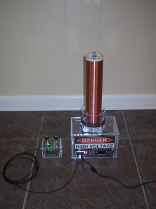
oneTesla tesla coil kit completed

Big Picture:
I was one of the first 100 backers of the oneTelsa Kickstarter (120 volt) and received one of their earlier kits (manual revision 1.3.0). Overall I was very happy with the kit. The overall build quality of the resulting Tesla coil (and especially the case) is much nicer than I could have achieved on my own without a kit, and the laser cut acrylic parts fit together very closely.
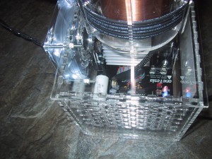
base_closeup

Because this is the first product the oneTesla team has shipped, and they are just starting out, some mistakes are expected. My kit did have one major problem: They accidentally shipped a 220 volt circuit board (for Europe or other countries that don’t use the 120 volt standard) and omitted the interrupter board entirely. Everything else in my bag of parts was set up for 120 volts. After a quick email to the oneTesla team they shipped me the correct circuit boards and I was able to solder them up. There were a few other minor hiccups with the kit (a missing screw, an extra fourth wire in the gate drive transformer pre-twisted wire set, weird reversed green LED’s, and a missing 2 pin jumper header that I replaced from my stock) but nothing else that was a real show stopper. The 1.3.0 manual was missing a few minor assembly steps, but nothing you couldn’t figure out from looking at the pictures and the parts lists, and most of those have been fixed in the 1.3.3 manual online.

Issues/suggestions for somebody else building a kit to think about:

Reversed Green LED’s
At least in the kit I received, the green LED’s were “backwards” in that the flat edge of the LED should be mounted OPPOSITE the flat edge in the circuit silkscreen. I believe they bought budget surplus gray market LED’s and got stuck with a batch with this weird manufacturing defect that a large company had rejected. This is documented in the errata online, and I didn’t make the mistake on the main board, but for some reason I didn’t remember to double check what color the LED was for the interrupter board. [Everything works with the LED reversed except you don’t get the power indication light ….but I decided it was worth fixing so that I didn’t accidentally run my battery down because I forgot to turn the interrupter off.]

Alternate Glue
They recommend using hot glue to affix all of the acrylic pieces. This would work, is somewhat reversible, and many people will already have a hot glue gun or can easily buy one locally. However, for the best visual appearance, I would recommend using acrylic welding solvent instead. Of course, acrylic welding solvent is scary stuff, so if you use it, read the warnings and wear nitrile gloves!

I used IPS Weld On 3 (McMaster Carr part number 7528A13) for both cases and the primary core base/clips. It will probably cost you as much as a hot glue gun to buy, but a one pint bottle will weld a LOT of acrylic. First, make sure you have the case assembled correctly, with all of the holes/slots lining up with the circuit board. Remember to try reversing the bottom piece if things are not lining up. Pay special attention to the slot where the wires from the primary core go into the screw terminals on the back. The cases are very nicely designed, but I wouldn’t have minded a few matching numbers etched in the corners to make it very easy to determine the exact orientation of each piece relative to one another.

After you are sure you have the cases assembled correctly (I held them together with rubber bands while testing), make sure that you can get your circuit boards into them from the top (they are a very tight fit, my case walls have to bend just slightly when inserting the main circuit board at an angle with a rolling motion).

To glue, lay the case down on it’s side with the base hanging off the edge of the table. (The base keeps the side pieces square.) Then use a q-tip to place a small drop of weld-on on the top of each tab that sticks up through the horizontal acrylic piece. You will see the water thin solvent wicking between the tabs and coating the bases of the joints between the tabs. I did one side (two sets of tabs) at a time with a ten minute wait between sides. Finally I turned the case upside down and affixed the base. Don’t glue on the tops!

For the primary core clips, I used clothespins to hold all six clips on. Make sure they are all straight and their spacing is evenly distributed. I used a coffee stir stick to place a small drop of acrylic welder on the top of the clip where it rests against the outside of the round acrylic primary form. After those set up (20 minutes) I took one clothespin off at a time and placed a drop of solvent on the top of the clip where it met the inside of the primary form, putting the clothespin back on to hold it in place for another 20 minutes. Finally, I turned the form upside down and placed a drop between the “U” bottom of the clip and the top of the form while rotating it slightly in my hand to use gravity to get the solvent to wick between the top of the form and the bottom of the clip’s “U”.

I did use hot glue to affix the top and bottom circles for the secondary core as that was an acrylic to ABS joint, which IPS Weld-On #3 isn’t good for, and it was a hidden joint anyways. I glued the bolt with magnet wire soldered to the terminal ring onto the acrylic circle while holding the bolt head in a pair of pliers, and used the wing nut to pull the bolt in tight. After the bolt was tight, I put extra hot glue all around the bolt head. Be sure to test your resistance between the bolts is less than 300 ohms (I got 228) before gluing the ends onto the secondary PVC pipe!
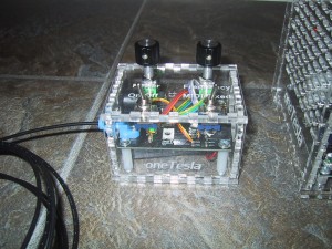
interrupter_closeup

Battery in the interrupter
I was a little worried about the lack of clearance between the metallic case of the 9V battery and the bottom of the leads and solder connections on my interrupter board, so I wrapped the battery in black electrical tape to make sure nothing shorted out.
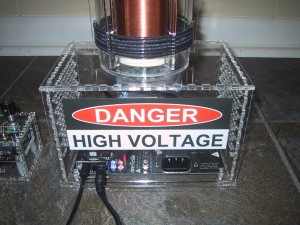
tesla_coil_base
Terminal substitutions
I substituted a ring terminal for the fork terminal they provided in the kit for the ground wire that affixes to the bottom of the secondary bolt. I feel the ring terminal is less likely to accidentally come off. Their assembly pictures shows a ring terminal on their demonstration model while the manual notes that they provide a fork terminal.

Instead of soldering a wire to the ground terminal on the top of the IEC power inlet, I bent the terminal upright and then used a crimp-on female spade terminal on the end of the ground wire to connect the wire to the IEC ground clip. I don’t plan on removing this connection, but this gives me flexibility for alternate grounding solutions if I need it in the future. For example, I can remove the ground wire entirely and replace it with a ring terminal going to an exterior ground. (It was also easier than taking the circuit board out of my case to solder the wire on, or trying to navigate my soldering iron inside the case.)

Velocity Cruz T301 Android Tablet review

I purchased a refurbished Velocity Cruz T301 Android Tablet for $70, and it was worth it. This tablet has many downsides when compared to many more expensive tablets, but the $70 price tag makes it a decent deal.

Pros:

  • Good screen quality – I’m quite happy with the screen brightness and color representation. It’s not a super high resolution, but it’s quite good for the price.

Cons:

  • Weight & size: At just over 1 lb, this 7 inch tablet feels heavy and thick. Although it was originally sold as an E-Reader + Tablet, I don’t think I would want to use it as an e-reader for long periods of time.
  • MIPS processor – Many android applications are pure Java and will work fine on the tablet, but a lot of the “best” games, video players, and high end applications use native code that is compiled for ARM processors, and are not compatible with the T301 tablet.
  • Lack of native flash support – The built in browser (due to the MIPS processor) does not support flash video, and I haven’t found a good substitute that does. It does have a youTube application that works, but it’s annoying to have to switch over to that application and re-find the movie. It also doesn’t work in various embedded contexts. The built in browser also does not support HTML5 video.
  • Touchy accelerometer – The screen would sometimes turn upside down when the accelerometer glitches. Not super frequently, but often enough that I eventually disabled the auto-rotate feature because I got tired of shaking the tablet to right the screen orientation.

I plan on using it as a dedicated screen (photo viewer, video monitor, etc) but with the right 3rd party apps (NewsRob/ K9 mail) it can be used for checking out your RSS feeds or reading your email.

Getting rid of extra UI elements in Google Reader!

My wife complained about all of the extra stuff at the top of Google reader. You know, the links to all of the other Google products in the black bar, the humongously big “Search Reader” bar and Google logo. I had never really minded them before, but it does take up around 150 pixels before you get down to your actual content!

Default Google Reader UI with lots of stuff at the top

So I searched around and found out that other people also dislike all the extra clutter and have designed scripts that will allow you to give the Google User Interface a haircut. If you are using Mozilla firefox, you can install the Stylish plugin and then the Google Reader Absolutely Compact style to get the following effect:

Google Reader after Stylish script to give the UI a haircut

Of course, the Stylish modification is a “one size fits all” super compact view. I actually like having access to the “Entry Actions” (keep unread, Email link, Plus One, etc…), so I ended up using the Google Reader Absolutely Customizable script for the Greasemonkey add-on, as it allows you to fully customize which elements are shown/hidden from within the Google Reader GUI (click on the “Subscriptions” drop down menu, select “Customize…” at the bottom.). Here is my final view of Google Reader:

Final customized google reader view

Spare One Phone – Dead on Arrival – Two Red LEDs

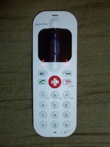
Spare One Phone with both indicator LED's glowing solid red

UPDATE: I called the company twice (once on Monday and again on Tuesday) and on Tuesday after asking a few questions they shipped me a new phone (arrived on Saturday and worked correctly!) and a label to ship back the defective unit. (I also emailed them on Sunday, and received an email reply 8 days later, after already receiving the replacement phone…so I would recommend persistent phone calls (it took a few tries to get to a human instead of voice-mail) over email.

Original post:
I purchased a SpareOne phone, which is a very simple GSM handset that is powered by a single AA battery. It has even less functionality than the Motorola MotoFone F3, as it has no display other than two indicator LEDs, so you can’t send or receive SMS messages. It comes with an Energizer Ultimate Lithium battery which has a 15 year shelf life (if you keep the battery disconnected from the phone with the provided plastic pull strip) and offers “up to” 10 hours of talk time on a single battery. My invoice number was 393, so it looks like I was within the first few hundred orders.

Unfortunately, when I received the phone and pulled the battery guard out, instead of turning on it just lit up both LED’s solid red (which I assume is some type of error code, although it is not mentioned in the small instruction sheet that came with the phone. I have tried a new battery, veracious press combinations of the ON button, and the keylock button, etc, but have gotten none of the feedback beeps demonstrated in the “how to” videos.

I will be calling their support line on Monday to see if they have any advice for how to re-set it, or return it for a replacement.

Book Recommendation: Midnight Never Come by Marie Brennan

Midnight Never Come by Marie Brennan is a work of historical fiction set in the court of Elizabethan England, and the corresponding faerie court below London. If you like historical fiction and fantasy, Marie Brennan has done a good job at both. Her historical research makes the world very detailed, but it’s the characters and plot that make this book truly captivating.

Review: MPJA 9615: 0-30 volt, 0-3 Amp, Bench Power Supply

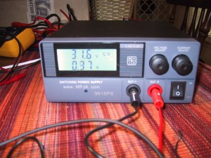
a small bench powersupply. Two knobs for volts/amps, and an on-off switch plus an LCD display.
This is the MPJA 9615ps mini-bench power supply. The specs say that it will provide 0-30 volts and 0-3 amps. Mine actually goes up to 31.6 volts (displayed, measured to 31.3 volts on my lowest DMM) and has driven a short at 3.25 amps (verified with my DMM). As the previous sentence alludes to, the voltage display on my unit was 0.3 volts higher than my $50 Chinese DMM, and 0.1 volts higher than my $14 Chinese DMM. Given that my two DMMs don’t quite agree, I’m not willing to say anything other than the fact that I think it’s accurate to at least 0.3 volts. [The amp readings matched those on my DMM’s.]

Pros:

  • The unit is nice and small.
  • The black on white backlit LCD is easy to read.
  • The price…this sucker costs $50!

Cons:

  • It doesn’t have a switch to turn off the output, so if you want to adjust it to a specific voltage before applying power, you have to disconnect it from your circuit, set the voltage, and then connect it to your circuit.
  • The knobs set the maximum voltage/current, but the LCD does not display the set value unless you are at the limit. So it typically displays the voltage set point (if the load is voltage limited), and if you want to set the current to a specific amount (higher than is currently being drawn) you’d have to short the leads or connect it to a dummy load. If you want to set the current to what the load draws or limit the current draw, you can start it off at zero and move it up until it hits the value you want.
  • The banana jacks to alligator clips the unit ships with are cheap. Notice those screw heads in the picture on the jacks? They are energized, so don’t touch!
  • The fan on the back runs continuously. It is not a terribly loud fan, but it is audible. (Think a laptop GPU fan that kicks in when you run a video game….except it never turns off.) This doesn’t bother me, but I wouldn’t leave the PS running all day either.

All in all, I’m happy with my purchase. This supply does what it’s supposed to and makes it easy to power circuits and monitor their power consumption. It makes a great inexpensive hobbyist bench supply, or a 2nd supply for a professional who just needs to power something.

Using the Microchip PIC Kit 1 with Linux

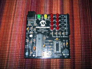
Microchip PICKit 1

The PICKit 1 is a combination programmer and development board for midrange PIC micro-controllers. In addition to being able to program FLASH pic devices, it also allows them to run and access 8 (charlieplexed) LED’s, a pushbutton switch, and a potentiometer. It’s a great little board for learning the basic of micrcontroller programing, but unfortunately it is not supported by Microchip’s new MPLAB X software (that is written in Java, and supports Linux/Mac in addition to Windows).

You CAN however use the PICKit 1 under linux. The piclab software is supposed to support it (I have not tested this). I use version 1.6 of the PicKit1 flash usb programmer for unix. Even the newest 1.6 version reports checksum errors after writing the hex file, but it does work correctly.

To make it work as an external program in MPLABX I had to select the “format HEX file for download” option under the Linker so that it would not fill all 2048 flash bytes when the program was smaller than that. I am able to manually run the usb_pickit command after building to flash the code, but it’s kind of annoying, as that program has a problem verifying the checksum and reports an error every time (which is interpreted as a build failure) plus, I have to run mplab X with root permissions to be able to access my USB port.