Daylight Savings Time MythTV wakeup failure

When I set up my MythTV box to suspend itself (and wake up whenever a show needed to be recorded) I followed the directions on the MythWiki ACPI Wakeup page, which suggested that I disable writes to the hardware clock as follows:

“Disable hwclock updates

On most machines it’s required to make a small change to the Linux shutdown procedure. When your machine goes down, most linux distributions write the system time/data back to the bios. On MANY machines, the machine never wakes-up after a time/data update. It’s recommended to make this change before you start. See below for more details (distro specific),

The reason for the recommendation above is that most linux distributions write the current system time back to the bios when shutting down the machine, and with some BIOSes, the machine will not wake up if the hardware clock is modified after the alarm timer has been set. To avoid that, it is necessary to disable the writing of the current system time to the hardware clock in the system shutdown scripts.”

This had no negative effects until daylight savings time kicked in. My MythTV box syncs itself over the internet, so it updated itself to daylight savings time with no problems. However, the system BIOS clock (hwclock) was not updated because I had disabled hardware clock updates! After a week of recording the very ends of shows instead of the full shows, I figured out what was happening and issued a “hwclock –systohc” command to re-set the BIOS (hardware) clock from the (correct) system time.

However, this will only work until daylight savings time ends, so I am investigating if I really need to disable the write to my hardware clock after the system sets the wakeup time. It may be that my BIOS handles that correctly, in which case I can take out the “HWCLOCKACCESS=no” line I added to my “/etc/default/rcS” file.

Canon S410 viewfinder problem

Our Canon S410 camera recently exhibited some strange behavior. When using the LCD display on the back as a viewfinder, it would display a shimmering curtain of pink and purple pixels instead of the correct view. The problem was not with the image sensor, because pictures could be taken normally, and it was not with the display, because when in playback mode the camera would display photos correctly. My best guess is that the camera CPU was using the wrong mode when moving the data from the image sensor to the LCD display when in viewfinder mode. (Icons would correctly display overlayed on top of the purple curtain). This error survied through multiple on/off cycles and removing the battery. Finally, I tried to shoot a video using the camera (which resulted in a video of the purple curtain that you see here), but when I switched away from video mode and back to video mode a second time the viewfinder started to work correctly! I’m not sure if it was specifically the video mode switch that caused it to fix itself, or just a large amount of mode shifts, but it’s working correctly again.

Motofone F3 working with AT&T Voicemail

A reader has reported that he purchased a Motofone F3 from “Monster-Cellular-Store” on ebay that came with a Cingular branded pleather case and it is set up to work correctly with the AT&T voicemail indicator system. The one I purchased however is still not working, so it appears that some setting or configuration is needed to make them work on the AT&T system. A picture of Neil’s phone and Cingular branded case is below:

Motofone F3 with Cingular branded case

Motofone F3 with Cingular branded case

I would love to know if some type of user configuration can be done with the keypad to make the voicemail work with AT&T.

Global search and replace in multiple files

Searching and replacing a bit of text in a lot of files is a very common problem. Lots of tools exist to get it done. On unix systems, awk is one favorite, and I found this webpage with a simple search and replace example.
Unfortunately, I wanted to search for \prob and replace it with %\prob. The difficulty is that the backslash character is “special”, so you have to escape it with other backslashes.

Here is my updated example command to run in each directory:

awk ‘{gsub(/\\prob/,”%\\prob”, $0); print > FILENAME}’ *.tex

It does a global substitution for the regex \\prob with string %\prob in the
whole input file ($0) for every file that ends in .tex

Bracket Assembly & Skate Bearings

Bracket & Bearing Assembly on Pipe

Bracket & Bearing Assembly on Pipe

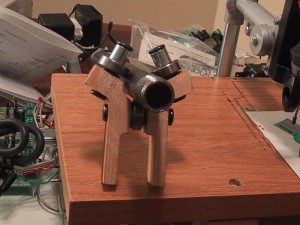
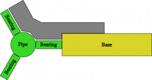
I manufactured a second copy of my bracket and used my hand drill to put a few holes in them to hold bearings. The idea is to mount 3 inline skate bearings at 120 degree increments around a pipe to limit motion to 1D (two of these on one side, plus two 2D mounts on the other side, make a Z-axis platform). I estimated the space taken up by the washers, and got it wrong, so if I wanted to use this design I will have to tweak my design and make a few “off-size” brackets to pair with the current ones I have. (Making all new brackets does not sound like fun, as each of them take almost 2 hours of routing time). The alignment and motion is a bit rough (I did eye-ball the holes) but I think I could improve upon that enough to make them passable with enough practice. However, due to the two-hour build time, I’m seriously considering using the “standard” angle-iron solution for my Z-axis.
Continue reading

CNC – First 2.5D cutting


I have designed a bracket that I used as my first attempt to manufacture something with my CNC mill. Because I’m still using python code I wrote myself and have not yet calibrated my stepper coordinates into real-world measurements, I had to design the bracket in Inkscape, print it out, and manually move my router bit to each point to determine the stepper coordinates along the path I wanted to cut out. This really sucked, and I plan on switching over to the parallel port controller board and EMC2 very soon so that I do not have to keep writing code. (I had to add code to cut out the bracket that interpolates between two endpoints so that I could route semi-accurate 60 degree lines.)

The piece of wood was secured Continue reading

First performance evaluation

Checking Accuracy

Scan of the circle test

Scan of the circle test

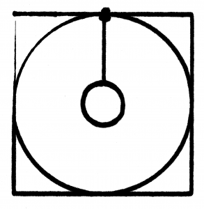
Using my simple router code I had the X/Y table plot a square with a circle inside of it (and then added some extra code to draw a smaller circle inside that). The first time I tried this I found that one side of my X/Y table was significantly (1mm or more) lower than the other. I added a washer between the table and the piece of wood that attached it to the Y-axis drawer pull and that improved things quite a bit ( the washer is on the bottom left corner of the test pattern). Using a felt tip marker gives a good indication of the level of the work platform, as the tip will be pushed up (and spread out, leaving a wider mark) if the table gains height, or get smaller if the table drops. One of my corners (top left in the image) has a distinct dip in it, but because I started the plotter at that corner and adjusted the height as it was moving I need to repeat the test. The giant ink spot in the top middle is because I left the pen sitting on the paper while writing the code to draw the inner circle.
Continue reading

New Serial Controller

I received the new and improved serial stepper controller board (version 4) from Ocean Controls. (Cost: 65 AUD) Although it supports up to a 6kHz stepping rate, I found that my steppers can only be driven at the RATE 12 setting, or approximately 745 steps a second. I’m not sure if this is because I’m not providing enough voltage or power (currently at 6v and 1.66A) or if that’s just the maximum rate of the steppers. When I try to use RATE 11, the steppers make nasty noises and are obviously loosing steps here and there. I don’t think it’s a current issue, as the usable RATE doesn’t change when running one stepper or two steppers at the same time. At some point in the future I’ll find a higher voltage power supply and see if that allows the motors to step faster.

This speed is still a small improvement over the original stepper controller, which worked at 605 steps a second maximum speed (despite the fact that it was supposed to run at 1000 s.p.s. or 1kHz). The documentation for the SSCB says that rate 12 is equivalent to 755.9 steps/second, so my measured 745 is relatively close, and probably is due to the built in acceleration and deceleration at the start and end of motion.

The real benefits of the version 4 board is the ability to start multiple motors at the same time, and get a prompt back over the serial line when the motors stop moving so I don’t have to poll the position (which still results in the controller board dropping steps). The new board also includes two command controlled relays, which will be perfect for turning on a spindle motor via program control, and perhaps enabling the stepper motor power supply.

The new multi-motor start command and feedback when finished greatly simplified the python code to interface with the stepper controller, and the serial control board no longer drops characters (perhaps because I am sending less characters and waiting patiently for motors to finish moving.)

Limit Switches: Important!

X-axis limit switches

X-axis limit switches


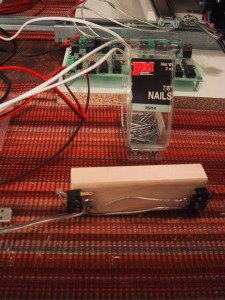
I have added limit switches to my X and Y axis. I always planned on adding them eventually, but after I stripped the nylon threads on one of my flange nuts in a router accident I decided that it was time. I’m using small micro-switches mounted such that they are closed when the X or Y axis nears the maximum extend of it’s motion. The ocean controls serial stepper controller has ports for limit switches on each axis, and when the circuit is closed that axis immediately stops moving and can only be moved one step at a time until the circuit opens again. I mounted the X-axis switches on a piece of wood from my 8 foot board I had to buy for the Y-axis pusher assembly (7.8 feet left!). I can’t decide what makes the router look more ghetto: The Ikea drawer rails, or the 45 degree screws holding the piece of wood down. (Also in the running is the blob of black epoxy-putty that pushes one of the X-axis limit switch.) Continue reading