Boost Converter Schematic

Schematic showing a 2 phase boost controller with voltage and current sense
I have drawn up a schematic (click to enlarge) of the high current and sensing portions of my maximum power point tracking (MPPT) 2-phase boost converter battery charger circuit.  The schematic does not include the micro-controller, MOSFET gate driver IC, and associated power supplies, as those items are on the (relatively) low-power side of things.

What do all of these things do?

  • L1, Q1, and D1 – These three components make up the heart of the boost converter. When Q1 turns on, power builds up in L1 as the current rises. When Q1 turns off, all of that power exits via the only available route (out past D1) and the voltage is boosted as the inductor (L1) resists the current change. If you turn Q1 on and off very quickly (under control of the micro-controllers’ PWM output via a MOSFET gate driver) it raises the output voltage higher than the input voltage.
  • Continue reading

Using the Microchip PIC Kit 1 with Linux

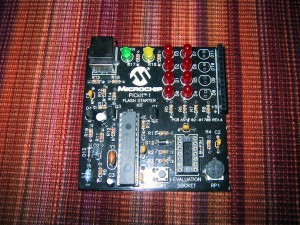
Microchip PICKit 1

The PICKit 1 is a combination programmer and development board for midrange PIC micro-controllers. In addition to being able to program FLASH pic devices, it also allows them to run and access 8 (charlieplexed) LED’s, a pushbutton switch, and a potentiometer. It’s a great little board for learning the basic of micrcontroller programing, but unfortunately it is not supported by Microchip’s new MPLAB X software (that is written in Java, and supports Linux/Mac in addition to Windows).

You CAN however use the PICKit 1 under linux. The piclab software is supposed to support it (I have not tested this). I use version 1.6 of the PicKit1 flash usb programmer for unix. Even the newest 1.6 version reports checksum errors after writing the hex file, but it does work correctly.

To make it work as an external program in MPLABX I had to select the “format HEX file for download” option under the Linker so that it would not fill all 2048 flash bytes when the program was smaller than that. I am able to manually run the usb_pickit command after building to flash the code, but it’s kind of annoying, as that program has a problem verifying the checksum and reports an error every time (which is interpreted as a build failure) plus, I have to run mplab X with root permissions to be able to access my USB port.

Solar Panels on the Electric Truck

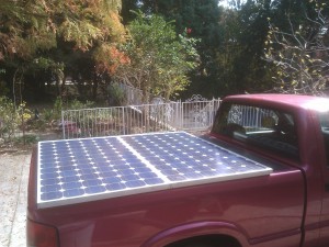
Two 175 watt solar panels mounted to the bed cover of my electric pickup truck.
I purchased two used GE Energy GEPVc-175 watt solar panels and mounted them to the bedcover of my truck using 10-24 machine screws and T cone washers as rubber vibration dampers. Each panel weighs 31 pounds, and is rated to deliver up to 175 watts of power in full sun (at around 36 volts each, or 73.4 volts at 4.7 Amps in series). I am still waiting on a group of Georgia Tech ECE students for the magic box that does maximum power point tracking (MPPT) and voltage boosting to charge my 120 volt battery pack, but I hope to be generating 1-3 miles of my daily commute from the sun soon. As my daily commute is 4 miles, this can be a significant percentage of my total energy usage.
Diagram showing the panel layout over bed cover support structure.

I have calculated that in the summer the panels are far enough behind the cab that they will not be shadowed by it, even if I have to park facing south. In the winter and early spring / late autumn I need to park facing north to avoid shading a strip of the solar panels.
I still need to figure out a way to tilt the panels towards the sun to collect as much energy as possible. This is especially critical during winter, when the solar angle is way off of vertical. As the bed cover tilts, AND the bed of the truck can tilt (the other way) I figure I can work something out (with a few pieces of wood cut to the correct height, or linear actuators if I want to get fancy.

Ferrofluid Sculpture test 2

After buying some strong rare earth magnets I re-tried my ferrofluid levitating sculpture. The main problem is that the ferro-fluid moves to the poles of the magnets (top and bottom, with gravity favoring the bottom) and does not surround the sides of the magnets. It was also hard to get enough small magnets to fit under the main magnet (as they repel each other), so I had to include a screw in the middle to get the weight correct.

Note: Working with Ferro-fluid is dirty and messy. If magnets snap together they can throw dark oily fluid which stains just about anything. Be sure to have lots of paper towels on hand, jars/shields under/around everything, and don’t work in a nice room. Dish detergent and abrasive scrubbing will eventually get it off of most surfaces that are not porous. Wear disposable rubber gloves and use disposable pipettes. Wear disposable clothes. Don’t use any of your wife’s kitchen appliances or instruments that you can’t afford to replace.

Update: After floating under the magnetic levitation for 24 hours, the ferro-fluid became much less “spiky” and eventually the drops at the end of the magnets became spherical.

Also, cleaning ferrofluid from a magnet is almost impossible.

Tracking individual battery voltages

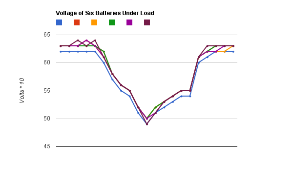
Line graph that shows the voltage of six batteries dropping under load. All six batteries follow the same deep V pattern, staying within 0.1 volt of each other.

This graph shows the voltage (multiplied by 10, so 65=6.5 volts, and 50 = 5.0 volts) batteries 1-6 of my electric pickup while accelerating. My first battery (blue) is consistently 0.1 volt below the others, so I am keeping an eye on it. But this graph shows that although it is a 1/10th of a volt lower, it does not sink lower than the other batteries under load, so it appears to be holding up well so far.

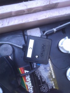
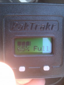
The graph also shows off my new (to me) Pak Trakr system. The Pak Trakr system connects to each battery in your pack with small remotes that daisy chain together. Each remote monitors six batteries and transmits the voltage levels once a second to a display and optional serial data logger.


Ubuntu 10.04 AMD Radeon M6 chipset and Extron Electronics video multiplexer

After working perfectly for 4.5 weeks with the same podium setup, my Thinkpad X31 laptop refused to output VGA video to the Extron Electronics video multiplexer box at school.
It appears that the Extron Electronics box is not sending out proper Extended Display Identification Data (edid) which tells the laptop what resolutions it supports. My xrandr command finds the data for my laptop video display screen, but not for the VGA-0 port:

VGA-0 connected (normal left inverted right x axis y axis)
LVDS connected 1024x768+0+0 (normal left inverted right x axis y axis) 0mm x 0mm
   1024x768       60.0*+   60.0
   800x600        60.3     59.9
   640x480        59.9     59.4

I have no idea why this started today. I don’t remember applying any patches to X-org in the last two days, and the technicians in charge of the podium swear that they didn’t change out anything.

I figured out a fix to make it (mostly) work. Tell xrandr to go ahead and force the VGA-0 port to a specific resolution with the following command:

 xrandr --addmode VGA-0 1024x768

This mostly works, but the sync signal is slightly off, leaving a black bar of 20-30 pixels on the left side of the screen. It is also annoying to have to run that command every time I want to display to the podium.

NetMedia iViewHD 2M POE Camera Review with ZoneMinder

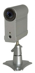
Small silver camera
I have recently purchased a NetMedia iViewHD 2M power over Ethernet (POE) camera (retail price $105) for use with ZoneMinder.

This small camera must be hard-wired into a switch that provides power over Ethernet (which will cost another $80-100, but allows you to power up to 4 POE devices). I bought mine used, and don’t plan on buying more. The one I bought would reset to factory defaults (requiring you to upload a new “website”) every few months, and after a year of use it died completely (won’t respond to DHCP address assignments). At used prices the NetMedia iViewHD 2M could be a good deal for daytime shots, despite my nighttime image quality complaints below, if the one you buy lives longer than mine, but I can’t recommend it.

Continue reading

On-Dash voltage guages

I received a VWRAS2-D12-D9-SIP isolated DC/DC power adapter from Digikey and built an updated voltage gauge module with dual gauges (one for the 12 volt accessory pack, and one for the 120 volt traction pack). The gauges were slightly too large to fit inside the dash, so I built an enclosure out of craft plywood that sticks out flush with the bottom of the radio.
Continue reading

HOWTO: Full Disk encryption on Ubuntu 10.04

How to set up an entirely encrypted disk using Ubuntu 10.04 (LTS):

    Use the Alternative installer (text based) ISO image so that you have access to the LVM and Encrypted Disk options.
    Assuming you want to keep a windows partition or some other pre-existing partitions intact, you will have to manually partition things instead of using the guided partitioner, so select “manual”.

Continue reading

S-10 Electric Pickup

Side view of the Electric S-10 Pickup
Our new commuter vehicle (and my new toy) is a second-hand electric conversion S-10 pickup. We purchased it from the original converter after he had upgraded to a Ford Ranger EV.

It is powered by 20 six-volt lead acid (PbA) golf cart batteries wired in series, giving a nominal 120 volt system. Sixteen of the batteries are stored in boxes under the tilt-up pickup bed. The remaining four batteries are under the hood, where the radiator would be on an internal combustion engine (ICE) vehicle. It can be charged via either the QuickCharge 120V charger plugged into a standard 15Amp outlet (which takes 13 hours) or the Zivan NG3 high frequency 240V charger (which takes 7 hours and a 240 volt outlet).

16 six volt batteries under the tilt-bed of the pickup
Continue reading