I purchased a surplus Currie Technologies “Diagnostic” throttle. (Which includes 3 LED’s labeled as 1/3, 2/3 and full charge indicators) It has a six pin (7 cable) connector with no pin-out diagram.
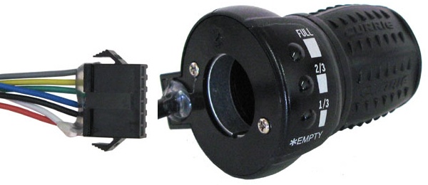
Currie Technologies diagnostic throttle
After opening it up, it appears that the blue, black, and red wires are connected to the throttle sensor itself, while the other four wires (White, Gray, Yellow, Green) connect to the LED circuit board.
The pin-out ordering is as follows, from the bottom of my picture up:
- Red/White (Throttle/LED, sharing a pin, + voltage)
- Black (to throttle, I assume Ground)
- Blue (from throttle, I assume signal)
- Green (Full LED)
- Yellow (2/3 full LED)
- Gray (1/3 full LED)
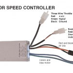
I connected the Red/Black/Blue wires to a motor speed controller that had a 3 wire throttle connection (matching them up to the Red/Black/Green wires from the controller) and it worked great!
The LED pin-out is as follows:
White (positive / Vcc)
Gray – 1/3 empty LED
Yellow – 2/3 full LED
Green – Full LED
Note that I was able to get the LED’s to light up with a 3V source, but I believe their forward voltage is less than 3V and you should use a current limited supply so that you do not burn the LED’s out.
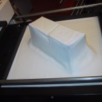
 After building a PVC pipe battery holder for my electric bike, I used a vacuum form machine to make a polystyrene battery cover. I built up a cheap tool form using cardboard (which turned out to be too week, but it was quick).