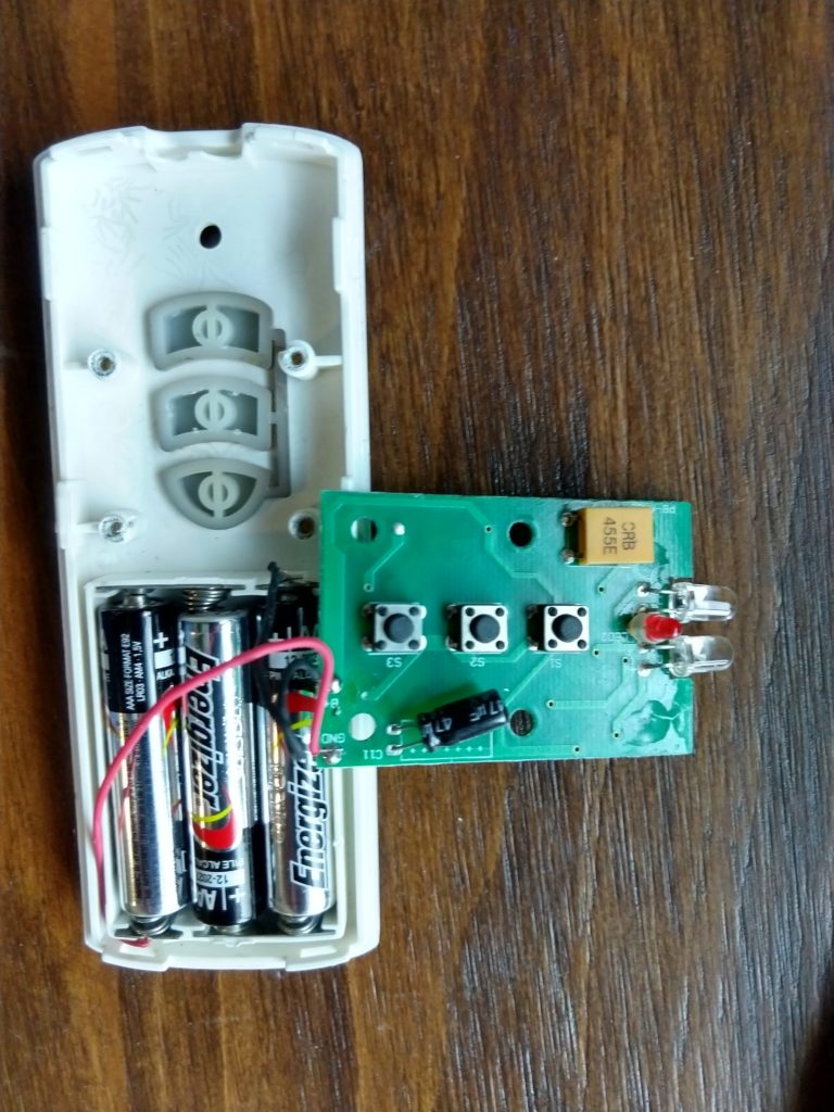
I have purchased three BEME Erod motorized drape systems (one in a previous house, and two in the current house). They have an infrared (IR) remote control that allows you to open and close the blinds at a push of the button, which is very useful if you have things in front of the blinds that make it hard to access the window, or if you just want to be able to open or close your blinds without getting out of bed.
Two of these units have worked flawlessly for several years. My third unit however has had two separate failures which I suspect may be due to poor quality parts.
The first issue crept up slowly, starting out as an intermittent delay in closing. The blind motor would make a “click” when you pressed the close button, but the motor would not engage for 20-60 seconds. Over time, the delay got longer and longer until eventually the blind refused to close. (Although the relay inside would still click when the button on the remote was pressed.)
Diagnosing this as a relay contact failure just from the sounds it made, I opened up the unit, found the part number on the relays, ordered replacements and (for good measure) replaced both relays. (I bought 5 of the relays, so I’m all stocked up for future relay failures.)
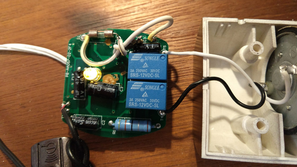
When I had the unit open, I noticed that there was one extra red “re-work” wire on the circuit board, indicating that the PCB had a problem (either a trace left out of the design, or not correctly connected on the PCB during manufacture.) and had to be repaired at the time of manufacture. This is actually more common than you might expect on inexpensive consumer goods, and since the motor was working well with the new relays, I closed things back up.
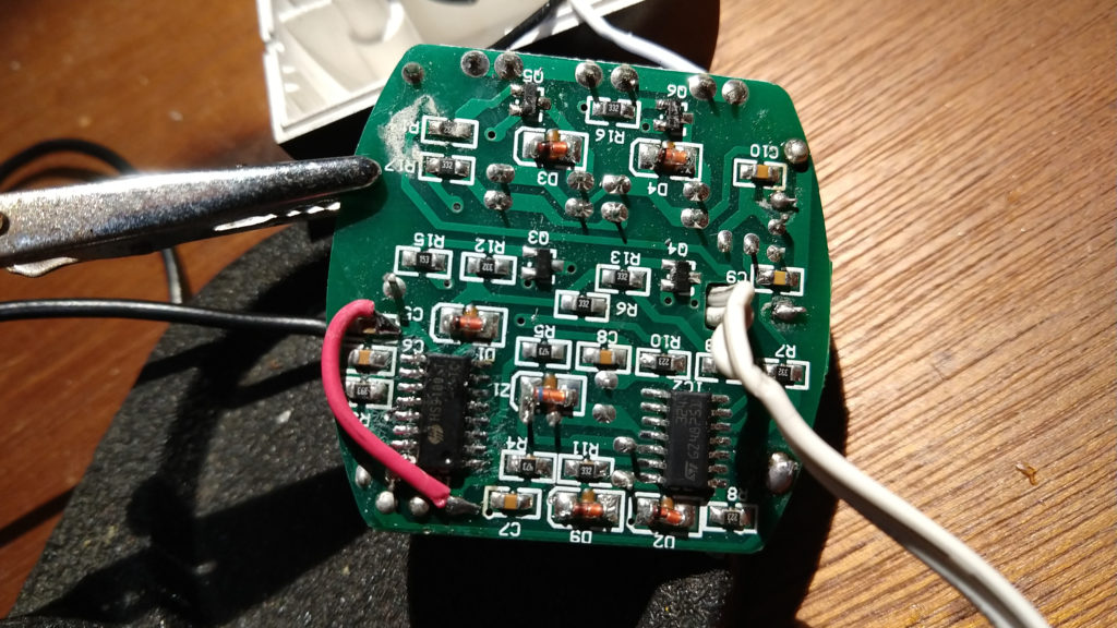
Around six months later, one night with no prior warning, the motor failed to respond to the remote control completely. No clicking, so the problem probably wasn’t the relays.
Here was my diagnosis procedure:
- I tried the remote on my other erod (despite the fact that the red light was lighting up when I pushed the buttons) to make sure the remote was working.
- Because the motor unit was acting as if it was not receiving any power (completely dead), I took the power adapter and tested to make sure it was providing power by using it on my other (working) erod.
- Now that I had determined that the problem was definitely with the motor unit, and not with the power supply or remote, I disassembled the motor unit.
- I checked the fuse on the circuit board, as it is the first possible reason power might not get into the circuit, but it was fine. (Also, a small yellow LED on the circuit board was dimly illuminated when plugged in.)
- I visually checked the capacitors to make sure that none of them were leaking.
- Since I had a diode tester mode on my multimeter, I checked all the diodes (but didn’t really expect them to have failed….)
- At this point, I noticed something funky on the circuit board. A small black component had one of it’s legs replaced by a resistor. (You’ll probably have to zoom into the photo to see it.) Normally, if a resistor is called for in a circuit, it will have its own location on the circuit board. This resistor was definitely added in later in the manufacturing process, and was not part of the original circuit board design. Since I hadn’t found anything else that would explain the failure, I felt that investigating this part was a good idea.
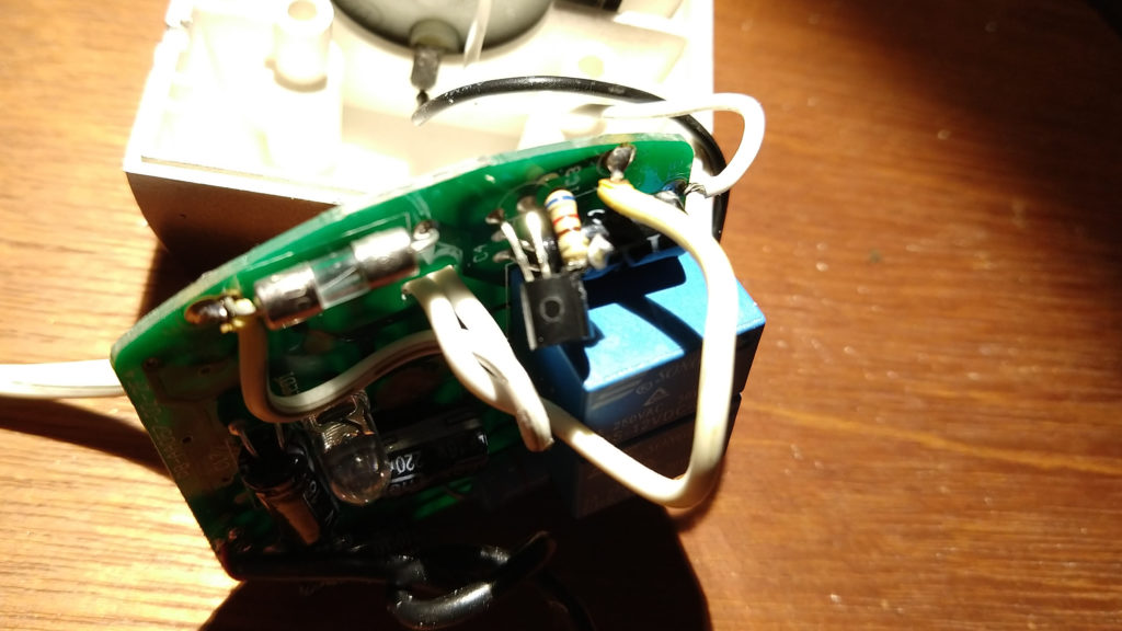
- The part is a 78L05 linear power regulator, which steps the 12v input down to 5 volts suitable for powering the microchips that watch for the IR remote control signal and trigger the relays (via transistors). The small yellow led was illuminating on the board when power was applied, so the 5 volt power rail should be working….but, the whole resistor leg looked dodgy to me. When I measured the voltage coming out of the 78L05 regulator, it was only 2.7 volts! (Just enough to illuminate the LED dimly, but not enough to run the other ICs.) After looking up the spec sheet to make sure that it wasn’t a 3.3 volt regulator, and really was supposed to be outputting 5 volts, I knew that either the power regulator was faulty, or something farther into the circuit was drawing so much power that it was not able to provide the proper voltage.
- I de-soldered the output leg of the power regulator from the rest of the circuit, and the output voltage went up to 5 volts, which hinted that the problem might be farther into the circuit. However, when I tested how much power the regulator could provide, it would only drive 17mA into a short! (A good regulator should provide 100 or 150 mA of power.)
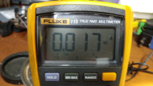
- I wasn’t sure if the resistor on the input leg was limiting the current that much, so I took the whole thing out and tried powering the regulator directly by bypassing the resistor, and it had the same low output current issue.
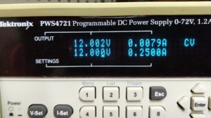
- So, time for a new 78L05 power regulator. This is a VERY common 5 volt regulator, and I happened to have one in-stock, which I soldered back into the circuit. I considered leaving in the input resistor (520 ohm), but decided against it, as the original circuit schematic obviously didn’t have that part, and according to the spec sheet, a 78L05 should be able to go from 12v down to 5v without problems. I measured the idle current draw of the entire motor unit afterwards, and it was only 8 mA, so the voltage regulator is dissipating 12-5 = 7 volts at 8mA, or 0.056 watts (5.6 mWatt) continuously, which is trivial even without a heatsink.
My suspicion is that the factory substituted an “off-brand” (or even counterfeit) 78L05 power regulator which they knew would have trouble dropping 7 volts, so they put a resistor in front of it to drop some of the voltage/power external to the power regulator, but the cheap part still failed. I’m hopeful that I have now replaced all of the parts that are likely to fail in this unit, and perhaps it will work well for me in the future.
