This is Hoja, a new (to me) 2013 Nissan Leaf. Hoja was rear-ended sometime around December or January, and was “totaled” by his insurance company, The Travelers Indemnity Company. They used Copart, an auto-auction company to sell the remains with a salvage title.
Continue reading
Tag Archives: etruck
Electric Pickup Truck: Cost of Ownership
We have owned an electric S-10 pickup truck for the last 1008 days (2.75 years) and used it as a daily driver. It was driven most frequently to the MARTA station, a 4 mile round trip commute, but also made trips to hardware stores, the Georgia Tech Campus, and to the homes of various people who were selling furniture or other larger items on craigslist. It uses twenty (six volt lead acid) golf cart batteries for its traction pack, and they have gradually lost capacity. When brand new, I would take the truck on 20 to 25 mile trips without stressing the battery pack. Recently however, the absolute maximum range of the truck had dropped to 12-14 miles and if you actually drove it 14 miles you could watch individual batteries hitting their absolute end of their state of charge. Although it could have functioned as a “Get to the MARTA station” vehicle for another year (or two?) I decided it was time to replace the pack to be able to comfortably go to the hardware store or make an extra emergency trip without worry. I have placed 685 charge cycles on the pack, which is in line with the lifespan for lead acid golf cart batteries.
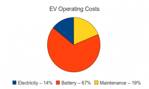
The replacement pack cost $2,171 (I gave back all but one of the used batteries for the core charge), which gives me the final piece of information needed to calculate the total cost of ownership over the last 1008 days. We spent $464 on electricity (estimated at $0.11 a KWH), $610 on maintenance, and the previously mentioned $2,171 on batteries. Obviously, the battery pack is the large cost here. In fact, the electricity cost is very small on a monthly basis, and was never more than 10-15% of our total KWH usage.
We drove a total of 4,861 miles in that timeframe, giving a cost of $0.66 a mile or $3.22 a day. This does not take into account licensing and insurance, but those costs would be exactly the same for an internal combustion engine (ICE) vehicle. If the S-10 were an ICE model, it would probably get around 20 mpg, so the fuel cost (estimating $3.50 for a gallon of gas) would be $0.175 per mile. So for 4,861 miles it would take 242.55 gallons of gas or a fuel cost of $849. This would imply that an ICE vehcile would have to have a maintenance cost of $2400 to get the same per mile cost of ownership as my EV.
Although ICE vehicles are more expensive to maintain, unless something major on the engine exploded, it looks like my hypotheical ICE S10 pickup wins the straight up cost comparison. Of course, I never had to drive out of my way to stop at a gas station, and there is the matter of 242.5 gallons of gas I didn’t use. (the lead and plastic in my batteries goes back to the factory to make new batteries)
In the interest of full disclosure, my first pack of batteries was purchased at a Sam’s Club for $1,800, so my true cost per mile is closer to $0.59. (But I used the pack replacement cost as an estimate for the cost of ownership for my next pack.)
I am hopefull that my 2nd pack (from Interstate batteries) will last longer, either because Interstate sells better batteries, or because I have learned how to care for them better. (Although I don’t think I did anything horrible to murder the first pack…)
Electric Truck Battery Pack Status Report
I’ve been driving my electric pickup truck since February of 2011, and have almost 2.5 years on my first lead acid battery pack (twenty six-volt GC-8 golf cart batteries by Energizer/Johnson Controls/Costco). I’ve put just under 2000 miles a year on the truck (4449 miles since I got it, 16011 miles total as an electric truck) but have charged the batteries around six hundred times. My average trip is relatively short (7.43 miles) and I’m averaging around 800 watt/hours per mile driven (measured from the wall, including charger and battery inefficiencies.)
When I first got the truck I could drive 20 miles with ease, and if I pushed things and drove carefully I could get up to a 30 mile trip out of the battery pack without pushing it below 80% discharged. Over the last 2.5 years / 600 cycles the pack has degraded, and one battery basically failed. I replaced the failed battery (it had about 1/2 the capacity of the rest of the pack and was limiting my maximum range to 5-7 miles per charge) with a replacement for $100 and now the pack is performing at a reasonable rate for a 2.5 year old set of batteries.
My current max range is around 15+ miles (I’ve driven several 13-14 mile trips carefully without getting any low battery alerts), which is enough to make it to the hardware store and back with a long piece of lumber. My typical commute is a 4 mile round trip to the MARTA station, so it can very easily make this trip. I expect that in the next year I won’t be able to make it to the hardware stores, but will probably still be able to use it to get to the MARTA station for a one or two more years.
I plan on replacing the entire pack in one or two years, depending upon how things shake out. It appears that my battery costs per mile will be in the 0.30 – 0.40 range, which is under the federal mileage rate, but does not count the cost of electricity (around 0.09 a mile) or maintenance. I have actually been very happy with the cost of maintenance on the truck. I replaced the two front shocks myself, had a shop service the brakes when I purchased it, and replaced a few pieces of interior trim and a parking break lever with parts I got at a junk yard, but all told the maintenance costs have been under $300 for the last few years. Compared to the maintenance needed on our internal combustion engine (ICE) vehicle this is a pittance…I could have bought two new battery packs for the truck with all the money we have spent on the family car in the shop over the last two years.
Boost Converter Schematic

I have drawn up a schematic (click to enlarge) of the high current and sensing portions of my maximum power point tracking (MPPT) 2-phase boost converter battery charger circuit. The schematic does not include the micro-controller, MOSFET gate driver IC, and associated power supplies, as those items are on the (relatively) low-power side of things.
What do all of these things do?
- L1, Q1, and D1 – These three components make up the heart of the boost converter. When Q1 turns on, power builds up in L1 as the current rises. When Q1 turns off, all of that power exits via the only available route (out past D1) and the voltage is boosted as the inductor (L1) resists the current change. If you turn Q1 on and off very quickly (under control of the micro-controllers’ PWM output via a MOSFET gate driver) it raises the output voltage higher than the input voltage.
Solar Panels on the Electric Truck
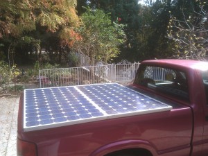
I purchased two used GE Energy GEPVc-175 watt solar panels and mounted them to the bedcover of my truck using 10-24 machine screws and T cone washers as rubber vibration dampers. Each panel weighs 31 pounds, and is rated to deliver up to 175 watts of power in full sun (at around 36 volts each, or 73.4 volts at 4.7 Amps in series). I am still waiting on a group of Georgia Tech ECE students for the magic box that does maximum power point tracking (MPPT) and voltage boosting to charge my 120 volt battery pack, but I hope to be generating 1-3 miles of my daily commute from the sun soon. As my daily commute is 4 miles, this can be a significant percentage of my total energy usage.

I have calculated that in the summer the panels are far enough behind the cab that they will not be shadowed by it, even if I have to park facing south. In the winter and early spring / late autumn I need to park facing north to avoid shading a strip of the solar panels.
I still need to figure out a way to tilt the panels towards the sun to collect as much energy as possible. This is especially critical during winter, when the solar angle is way off of vertical. As the bed cover tilts, AND the bed of the truck can tilt (the other way) I figure I can work something out (with a few pieces of wood cut to the correct height, or linear actuators if I want to get fancy.
Tracking individual battery voltages
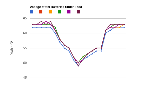
This graph shows the voltage (multiplied by 10, so 65=6.5 volts, and 50 = 5.0 volts) batteries 1-6 of my electric pickup while accelerating. My first battery (blue) is consistently 0.1 volt below the others, so I am keeping an eye on it. But this graph shows that although it is a 1/10th of a volt lower, it does not sink lower than the other batteries under load, so it appears to be holding up well so far.
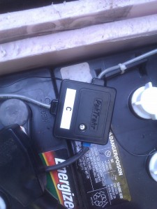
The graph also shows off my new (to me) Pak Trakr system. The Pak Trakr system connects to each battery in your pack with small remotes that daisy chain together. Each remote monitors six batteries and transmits the voltage levels once a second to a display and optional serial data logger.
New voltage gauges

This picture shows off my new flush-mount laser cut panel with voltage meters installed. These new gauges are Datel self-powered LED voltage displays (DMS-20PC-8-DCM for the red traction pack display and DMS-20PC-0-DCM-B for the blue accessory battery display). They are considerably more expensive than my previous gauges ($50 for the red and $59 for the blue) but have two major advantages. First, they actually fit inside the dash, so I can flush mount them instead of building a box around them. Second, they are “self-powered”, which really means they have their own DC/DC converter built in and draw power from the source they are monitoring. But, because each gauge has it’s own DC/DC converter, they are completely isolated from each other (something that my previous “isolated” DC/DC converter didn’t really do well.) Having all the power circuitry integrated into the gauge also greatly simplifies the wiring.
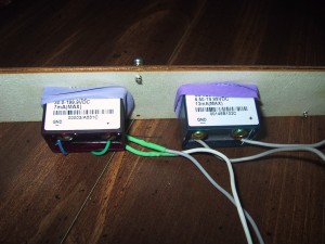
The gauges come with metal clips to fix them to the back of a panel, but the clips were too big for my opening. I improvised with a very close fit on the cutouts and some large rubber bands. If I ever need to replace the rubber bands, I just unscrew the four 6x 5/8 inch screws to remove the panel. (The screws are not exactly balanced on the panel as I was matching up to pre-existing holes.)
I wanted two different colors for the accessory and traction pack voltage, so I paid $9 extra to buy the blue LEDs for the 12 volt accessory battery. It turns out that this was a mistake. The blue gauge is much brighter than the red one, and at night it is blinding. I wired up a toggle switch to allow the driver to turn it off when driving at night. (The red gauge is just right, easily visible in the daytime but not too bright at night.) If anybody wants to buy a blue self powered voltage gauge for $50 including shipping I’d gladly sell it and buy a red replacement.
On-Dash voltage guages
I received a VWRAS2-D12-D9-SIP isolated DC/DC power adapter from Digikey and built an updated voltage gauge module with dual gauges (one for the 12 volt accessory pack, and one for the 120 volt traction pack). The gauges were slightly too large to fit inside the dash, so I built an enclosure out of craft plywood that sticks out flush with the bottom of the radio.
Continue reading
120 Volt Charging Plug
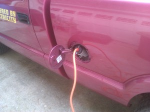
Our “new” electric pickup came with a 240 volt twist-lock connector where the gas cap would be. This is great for plugging into a 240 volt outlet, such as used by an electric range or clothes dryer, but we are primarily charging it with a 120v convenience charger. (So called because 120v outlets are more convenient to find. It actually takes about twice as long to charge using 120v so from a time standpoint it is less convenient.)
I decided to add a second 120 volt plug behind the fuel port door so that I could plug in either voltage cable. Continue reading
Building a PVC Vacuum Reservoir

The electric pickup truck uses a vacuum pump to generate vacuum for the power brakes (and move vents in the HVAC system). It has a pressure switch that turns on the pump when the vacuum drops to under 15 inHg and turns it off once the pump has raised the vacuum to 25 inHg. The current system has a small 3″ by 1.5″ PVC cylinder as the vacuum reservoir. As soon as you press the brake the pump turns back on, and cycles on and off relatively frequently. I wanted a larger vacuum reservoir so that the duty cycle on the pump would be longer (it would stay on longer, but also stay off longer) and so that even when the vacuum drops to 15 inHg I could still operate the brakes several more times while the vacuum pump was working.
Continue reading

