How to build custom length high current cables

IMG_20151025_203133

IMG_20151025_202930

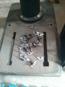
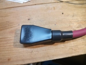
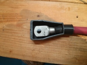
When wiring up an electric vehicle traction pack battery, an off-grid battery backup bank, or other high current power systems, you sometimes need a cable capable of handling high-current with a custom length. If you have a few tools, it is easy to make your own by crimping terminals onto welding cable. This video shows a time-lapse overview of making such a cable:

Here is a set of links to the tools and materials I used:
Continue reading

Battery carrier compatibility, location specific modifications

battery_pickup_tool

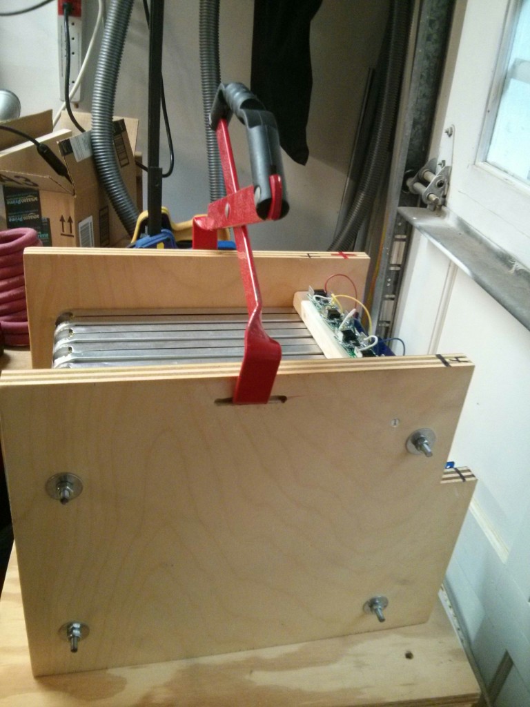
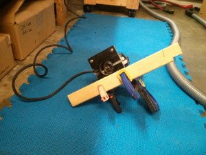
This is a Battery Carrier tool designed for picking up and carrying around lead acid batteries (golf cart or starter batteries). I own one because it’s very useful when removing 20 golf cart batteries from my S-10 electric pickup truck and replacing them with 20 new batteries. While manhandling my Nissan Leaf batteries around my garage, I though “Boy, it sure would be nice to be able to use my battery carrier on these guys.” A few minutes spent rigging up a jig for my trim router and vacuuming up a lot of saw dust later, each of my batteries has a small slot cut in both sides…

plunge_router_with_guide

slots_in_battery

I had thought that I would have to sell my battery carrier and battery filler now that I am upgrading to Lithium Ion…I guess only the battery filler will be obsoleted.

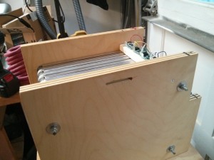
I also modified a few of the batteries to better fit in my existing battery bays. Specifically, I decided that batteries 1&2 and 7&8 would be mounted “back to back” and I didn’t need each of them to have a full 1″ of space at the bottom, so I cut a 1/2″ off the bottom of each, giving me an extra inch of room, and leaving them a shared 1″ air vent.
batteries_7_8_back2back

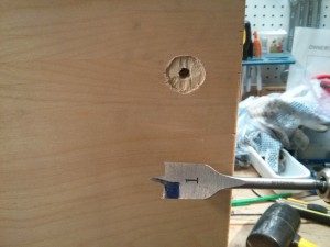
On battery 3, which will be mounted “sideways” with respect to batteries 4,5 & 6, I used a spade bit to sink the washer in a little, and cut off the ends of the threaded rod to make sure they wouldn’t interfere with cables.

battery_3_shortrods

one_inch_indentation

extra_long_rods_cutoff

How to build a 16 volt battery module from six Nissan Leaf cells

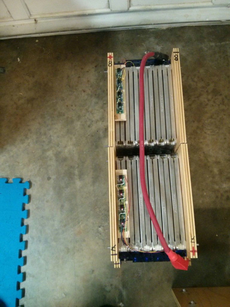
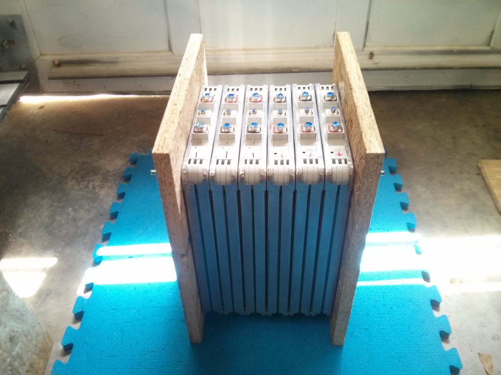
I am building 16 volt batteries using six Nissan Leaf LiIon cell modules. (A Nissan Leaf battery has 48 modules, supplying the construction of 8 of my “batteries”.) My Battery is arranged in a 3P2S (two sets of 3 parallel modules in series), giving a 180 Ah capacity and nominally 16 volts (each module from a Nissan Leaf has 2S2P cells inside, so the module goes up to 8.4 volts maximum at 60AH).

This video (playing at 4x-16x speed) shows all of the work that goes into building a battery. Directions with more information are below.

To build a battery, here are the parts you need:

  • Two end plates, made from steel or plywood.
  • Six nissan Leaf modules, sandwiched between the end plates.
  • Four pieces of threaded rod, 10.5 inches in length, with the following hardware for each rod:
    • Two nuts
    • Two lock washers
    • Two fender washers
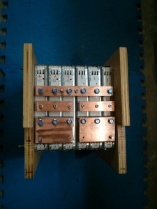
  • One 7.5″ x 1″ x 0.25″ copper bus bar (to make the series)
  • Two 3.5″ x 1″ copper bus bars (to join the sense terminals) I used 0.25″ thick so that I could source it from the same copper as the series busbar above, but this is overkill, you could use 0.125 or even smaller.
  • Two 3.5″ x 2.5″ x 0.25″ copper bus bars (to be the + and – terminals of the main battery).
  • 12 M6 bolts (can re-use the ones that came with the leaf modules)
  • 12 M6 Locking washers (I used Belleville Spring lock washers)
  • six M4x16 machine screws for the sense terminal bus bars
  • six M4 locking washers (I used Belleville spring lock washers)
  • three M4x8 machine screws for the BMS terminals + 5 more lock washers
  • Two 5/16th bolts (1″ or 0.75″) for the + and – terminals. (could substitute 1/4″ or metric bolts, I used 5/16th because that is what golf cart batteries use.)
  • (very optional) one more 5/16th bolt for the series bus bar if you want to attach a 5/16 ring terminal from an existing battery monitoring system to each “8 volt” half of your battery.
  • 12×12″ acrylic sheet to laser cut battery cover from.

Continue reading

Laser cut acrylic terminal covers

cover_with_bms_topview

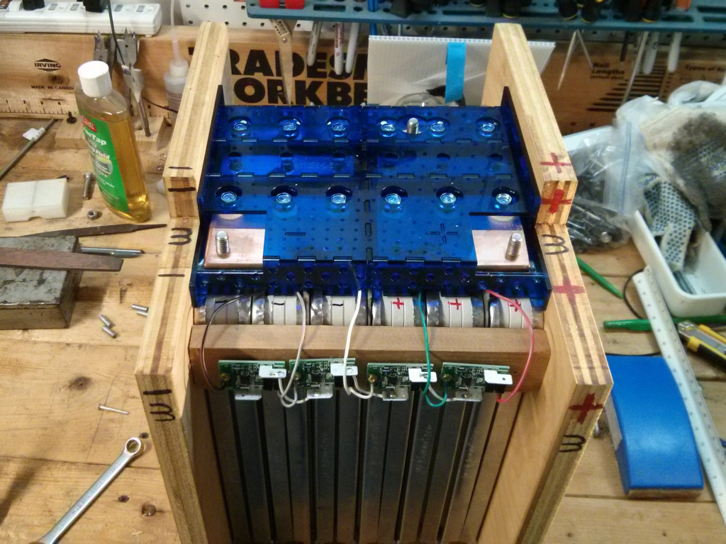
I laser cut some covers that place an acrylic wall between each of the busbars of my battery, as well as covering the top. They are designed to keep a falling screwdriver, wrench, or bolt from bridging the bussbars and causing “excitement”. I have a lot of air holes to try and allow a normal amount of air flow, as well as exposing the bolts and screws for occasional tightness checks.

busbar_layout

You can download the textual openscad design file here:
battery_shield.scad

Or, you can just download the PDF files if you want to laser cut them exactly as they are:
battery_shield
battery_shield_reversed

A “how to assemble” video is here:

Youtube Video link

Acrylic could be a bit brittle for this application, and using 3mm craft plywood could provide a bit more impact resistance. However, the covers are inside the “sidewalls”, plus the batteries will be mounted sideways and the current “top” will be mostly protected by insulating foam in my battery boxes,so I chose to go with the less smoky option. (Plus, I think the semi-transparent nature of the acrylic just looks cooler.)

Leaf battery module differences – 36 “normal” and 12 “special”

The 2013 Nissan Leaf battery pack that I disassembled had 48 battery modules in it. Previously, I had separated the modules that were in the front half of the pack, packed in stacks of 2 or 4 “flat packed”. However, I had only removed the 24 modules are located in the back of the pack (under the passenger seat) as a unit, and had not unpacked them yet. When I unpacked them, I discovered that 12 of the modules (every other one) had some differences from what I consider to be the “normal” modules (the other 36).
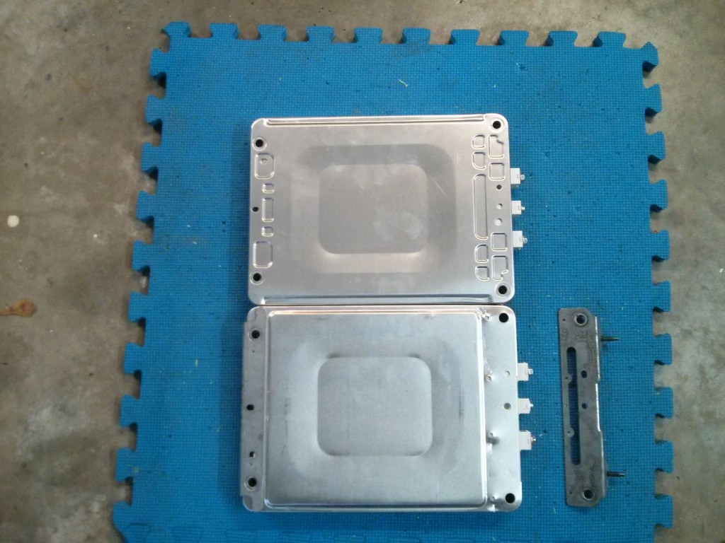
module_differences_mounting_plate4
In the picture above, a “normal” module is at the top, while one of the 12 “special” modules that supports the mounting brackets is on the bottom, with the removed mounting bracket. Note how the tin plate sticks out a little bit more on the “normal” module, taking up the same amount of space as the steel mounting bracket on the “special” module.

The “special” modules have small metal plates that mount to the top and bottom of the modules. These metal plates then bolt into support brackets, which allows this set of 24 modules to be supported “sideways”. I started to worry that these extra pieces of metal would change the spacing of the modules (from my previously measured 1.3333 inches per module), but as it turns out they don’t. The modules themselves are shaped slightly differently (just a bit narrower at the top and bottom) to allow for the extra width of the steel mounting brackets. The main body of the modules should still be compressed to 1.333 inches in size.

Looking inside, the pouch cells extend up past the main body just slightly, so I decided to leave the steel plates on as shims, but cut off the bolts as they would get in the way of my busbars. The bottom of the pouch cells don’t extend appreciably past the main body on the bottom, so I’ll be leaving the bottom steel plates off.
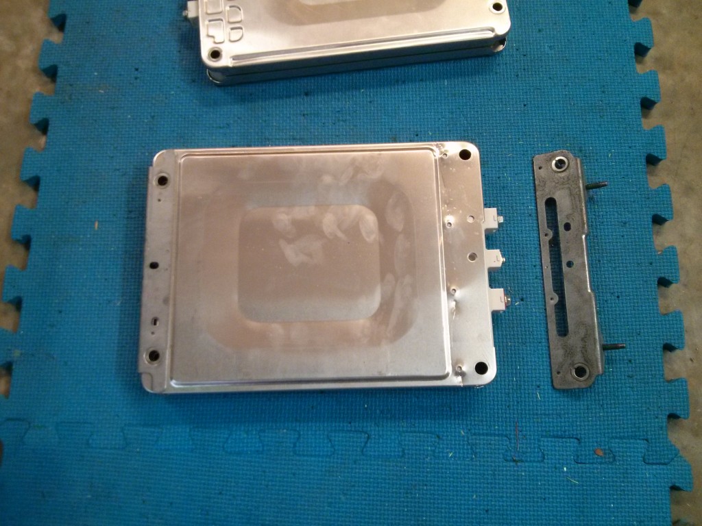
module_differences_mounting_plate3

The metal plates have circular tube like supports that reach inside the holes on the modules, supporting them, and are also spot welded to the thin “tin” outsides of the modules. They can be pried off with a flat bladed screwdriver, popping the spot welds out and leaving small holes in the tin plates.

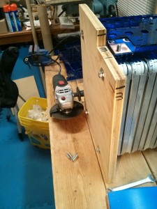
I just used a cut off blade on an angle grinder to cut off the parts of the brackets that I don’t want hanging out on the top of my battery.
modified_steel_panel
screwtops_cut_off

Battery Bay Plan: Nissan Leaf Cells six group

SixGroup

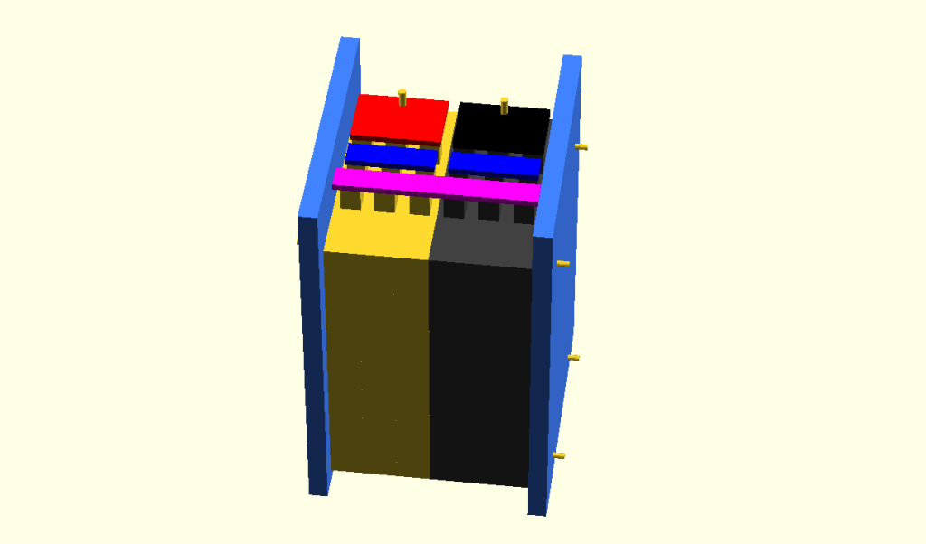
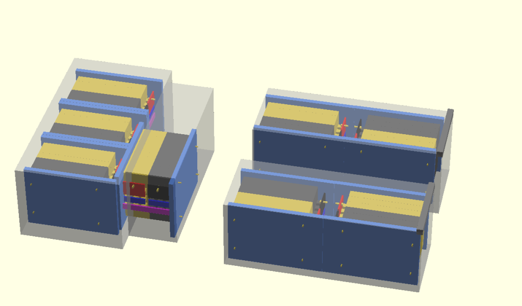
This is my current CAD mockup of how I will package a group of six Nissan Leaf modules. I have 48 total modules from a Leaf battery, so I will have eight of them to distribute throughout my truck’s battery bays. I also have a CAD model of that:
batteryBays

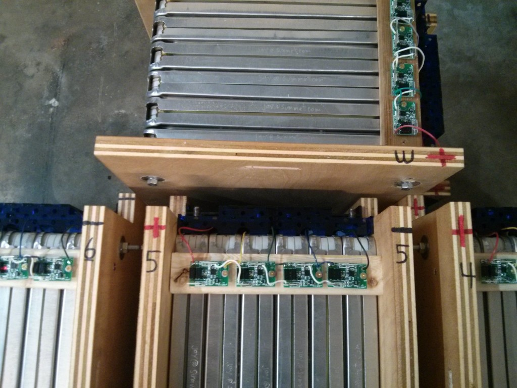
Unfortunately, my existing Lead Acid (golf cart battery) bays are not tall enough to mount them vertically, so I am having to lay them sideways. This results in terminals being relatively close together in the two side bays. (I’ll probably slide a sheet of plastic between the two batteries after I get them installed to make it more difficult to drop a wrench down there and short things out. It’s only 32 volts total potential, but a lot of Amps!)

If you would like to know the specifications of a single module (and some people have asked) here is what I know:

From: http://www.electricvehiclewiki.com/?title=Battery_specs
Confirmed by Jay with a 2013 Nissan Leaf module.

lm_width=223; // mm – 8.7795 inches (measured 222 – 8.75 inches)
lm_length = 303; // mm – 11.9291 inches (measured 298.45 or 11.75 inches)
lm_thickness = 34; // mm – 1.3779 inches (measured 34- 1.3333 when compressed)
lm_weight = 3.8; // kGrams, or 8.3775 lbs

The power “bolt blocks” are 20×20 mm in size, and I modeled them around 1 inch in height. But, this height includes the space for a bolt head and a busbar on the top. In the CAD model I made them one inch tall, but in real life they are slightly shorter than that. The “bolt blocks” for the sense terminals in the middle are slightly smaller (18×18 mm) but the same height. So if you download my CAD model (link below) keep in mind that the top of the bolt blocks on the module includes a little extra wiggle room. The CAD software I use is OpenSCAD, which you can download for free. The file itself is human readable text.

BatteryPacks.scad (You may have to rename it from BatteryPacks.scad.txt to BatteryPacks.scad )

Building a battery from Leaf Modules – The Plan

I am in the process of replacing the twenty (20) six volt lead acid golf cart batteries that power my electric pickup truck with 48 Nissan Leaf battery modules. Because the battery bays in the truck are specificity designed to hold 20 golf cart batteries (and the Leaf modules have a different form factor), it’s not a straight-forward drop in replacement.

My initial design (not showing the compression plates that hold the six modules together in compression):
sixGroup
In the image above, the black bar is negative, Continue reading

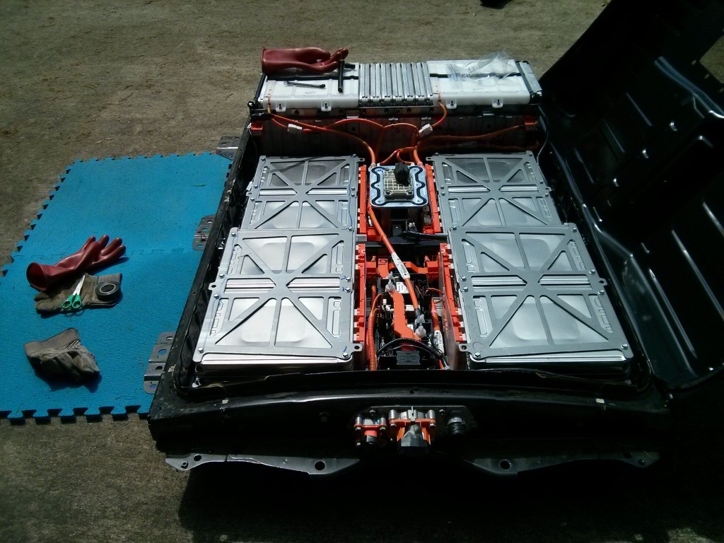
How to open a 2013 Nissan Leaf battery pack and remove the modules

battery_open_front

I have opened my 2013 Nissan Leaf battery pack and removed the modules. The tools needed are:

  • 500 volt class 0 (or better) electrically insulated gloves
  • One or two full rolls of black electrical tape, for covering your tools and the terminals of the modules when you remove them.
  • Regular leather gloves
  • Side clippers and needle nose pliers for removing wire tiedowns
  • 1-1/2″ putty knife or chisel and hammer. (or preferably an air chisel)
  • 10 mm wrench (preferably a socket with ratchet)
  • 13 mm deep socket
  • 16 mm wrench and hammer (or impact driver w/ 16mm socket)
  • small flat bladed screwdriver for prying clips
  • # 1 Phillips screwdriver for removing screws on the sense terminal of the modules

You can watch the 13 minute youtube video here, or spend about the same amount of time wading through my wall of text below….

First: Remove the twelve 10mm bolts Continue reading