Z-axis cart and adjustment assemblies

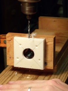
Drilling the holes for the adjustment screw

Drilling the holes for the adjustment screw


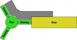
I cut out the parts for my Z-axis assembly using a jigsaw, and while butting the machine edges worked fine the other edges were a bit sloppy. I took advantage of an in-law’s shop to finish them up with a table saw and now the edges are much nicer. The base dimensions of my Z-axis are 11 inches by 10 and 1/2 inch, and the sides are 2 and 1/2 inches high. My 12 inch black pipes are mounted with their centers 7 and 1/2 inches apart using adjustment assemblies made out of an old plastic cutting board. My Z-axis cart is just slightly over 5 inches square.
Continue reading

CNC – First 2.5D cutting


I have designed a bracket that I used as my first attempt to manufacture something with my CNC mill. Because I’m still using python code I wrote myself and have not yet calibrated my stepper coordinates into real-world measurements, I had to design the bracket in Inkscape, print it out, and manually move my router bit to each point to determine the stepper coordinates along the path I wanted to cut out. This really sucked, and I plan on switching over to the parallel port controller board and EMC2 very soon so that I do not have to keep writing code. (I had to add code to cut out the bracket that interpolates between two endpoints so that I could route semi-accurate 60 degree lines.)

The piece of wood was secured Continue reading

First performance evaluation

Checking Accuracy

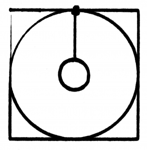
Scan of the circle test

Scan of the circle test

Using my simple router code I had the X/Y table plot a square with a circle inside of it (and then added some extra code to draw a smaller circle inside that). The first time I tried this I found that one side of my X/Y table was significantly (1mm or more) lower than the other. I added a washer between the table and the piece of wood that attached it to the Y-axis drawer pull and that improved things quite a bit ( the washer is on the bottom left corner of the test pattern). Using a felt tip marker gives a good indication of the level of the work platform, as the tip will be pushed up (and spread out, leaving a wider mark) if the table gains height, or get smaller if the table drops. One of my corners (top left in the image) has a distinct dip in it, but because I started the plotter at that corner and adjusted the height as it was moving I need to repeat the test. The giant ink spot in the top middle is because I left the pen sitting on the paper while writing the code to draw the inner circle.
Continue reading

New Serial Controller

I received the new and improved serial stepper controller board (version 4) from Ocean Controls. (Cost: 65 AUD) Although it supports up to a 6kHz stepping rate, I found that my steppers can only be driven at the RATE 12 setting, or approximately 745 steps a second. I’m not sure if this is because I’m not providing enough voltage or power (currently at 6v and 1.66A) or if that’s just the maximum rate of the steppers. When I try to use RATE 11, the steppers make nasty noises and are obviously loosing steps here and there. I don’t think it’s a current issue, as the usable RATE doesn’t change when running one stepper or two steppers at the same time. At some point in the future I’ll find a higher voltage power supply and see if that allows the motors to step faster.

This speed is still a small improvement over the original stepper controller, which worked at 605 steps a second maximum speed (despite the fact that it was supposed to run at 1000 s.p.s. or 1kHz). The documentation for the SSCB says that rate 12 is equivalent to 755.9 steps/second, so my measured 745 is relatively close, and probably is due to the built in acceleration and deceleration at the start and end of motion.

The real benefits of the version 4 board is the ability to start multiple motors at the same time, and get a prompt back over the serial line when the motors stop moving so I don’t have to poll the position (which still results in the controller board dropping steps). The new board also includes two command controlled relays, which will be perfect for turning on a spindle motor via program control, and perhaps enabling the stepper motor power supply.

The new multi-motor start command and feedback when finished greatly simplified the python code to interface with the stepper controller, and the serial control board no longer drops characters (perhaps because I am sending less characters and waiting patiently for motors to finish moving.)